
switches Using a momentary push button as a latching on-off toggle switch
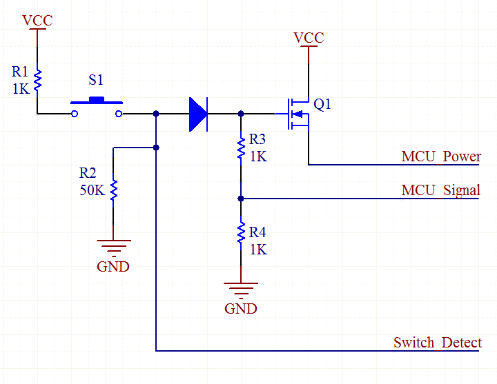
The circuit described is a power control system utilizing a microcontroller and MOSFETs to manage the power supply through a push button mechanism. The TPS_EN line serves as the enable signal for the power regulator, which is initially held low by a pull-down resistor. This ensures that the regulator remains off until user interaction occurs.
Upon pressing switch S2, a ground signal is applied to the gate of MOSFET Q2, turning it on. This action allows the TPS_EN line to transition from low to high, thus enabling the power regulator. The regulator then powers the microcontroller, which is responsible for controlling the state of the latch outputs, LATCH_OP1 and LATCH_OP2. When these outputs are pulled low by the microcontroller, they activate Q2 and Q6.
The activation of Q6 creates a high signal at the terminals of switch S2, indicating that the system is ready for further user interaction. LATCH_OP1, by latching Q2, maintains a high signal on the enable line (VBATT), ensuring that the regulator remains powered as long as the button is pressed.
However, upon subsequent presses of the button, the circuit behavior changes. With Q6 already on, the application of VBATT to the gate of Q2 results in the deactivation of Q2, which in turn disables the power regulator. This sequence powers down the microcontroller, causing both latch outputs to revert to their high state. The intended operation of the circuit is disrupted at this stage.
The issue may stem from the interaction between the microcontroller's output states and the latch control mechanism. The manual adjustment of the latch lines to ground suggests that the microcontroller's control logic may not be correctly configured to maintain the desired states for LATCH_OP1 and LATCH_OP2 during operation. A thorough examination of the control logic and the timing of the signals is recommended to ensure proper functionality of the circuit as intended. Additionally, reviewing the connections and ensuring that there are no unintended shorts or floating signals may help resolve the operational discrepancies observed.An explanation of how the thing should work. The TPS_EN line is low at first. Since it is pulled down by a 10k pull down resistor(not shown in the schematic). When the user presses S2, the mosfet Q2 turns on because ground is applied to its gate. which enables the power regulator connected to the TPS_EN line. The regulator now starts up and starts powering the microcontroller. The microcontroller pulls the LATCH_OP1 and LATCH_OP2 low. The mosfet Q2 and Q6 now `turns on` due to this. Q6 is turned on and now causes the 1st and 2nd terminals of the push button s2 to go high. And the LATCH_OP1 causes the Q2 to latch thus enabling a constant high signal (VBATT)on the enable line. Now when the user presses the button Since Q6 was `on` the VBATT gets applied to gate of Q2 and turns off Q2.
The regulator turns off. turning off the microcontroller and the LATCH_OP2 and LATCH_OP1 return to VBATT. The circuit does not work as intended. I tried manually changing the latch lines to ground when turning on and it worked. But when i connect the lines to the microcontroller it does not work Please help me out! 🔗 External reference
Related Circuits
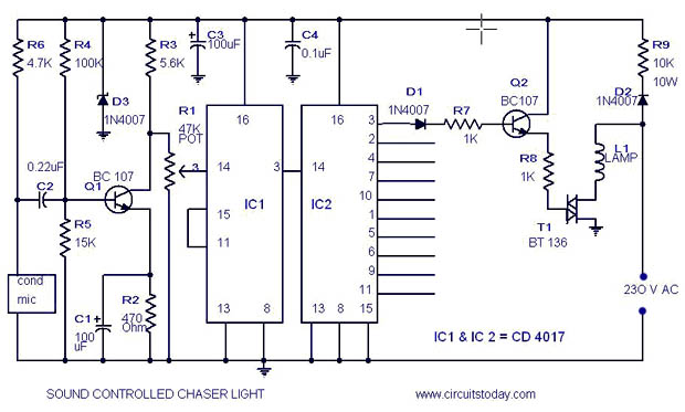
A simple musical light chaser circuit diagram and schematic using IC CD4016. This circuit blinks lights in response to sound, audio, or music output, causing 10 lights to dance according to sound frequency. The musical light chaser circuit utilizing the...
Pure A class is the most simple topology for designing an amplifier. The tube or the power transistor is loaded directly by the speaker (often through a transformer, for impedance matching), and is biased at the current necessary for...
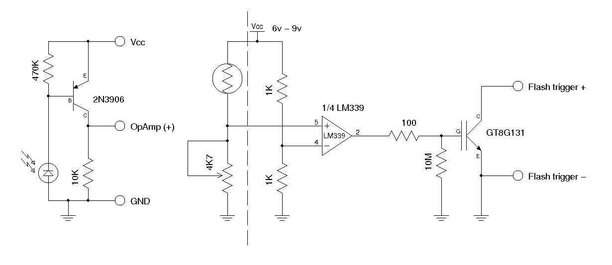
A synchronous camera flash, such as a slave flash, is typically triggered using a silicon-controlled rectifier (SCR). This document presents a circuit designed to trigger a secondary camera flash utilizing an insulated-gate bipolar transistor (IGBT). The use of an...
This circuit is designed for children's entertainment and can be installed on bicycles, battery-powered cars, motorcycles, as well as models and various games and toys. When switch SW1 is positioned as indicated in the circuit diagram, it generates the...
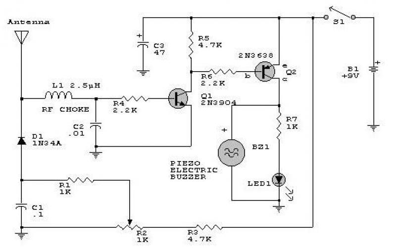
This circuit responds to RF signals below the standard broadcast band up to over 500 MHz and provides both visual and audible indications when an RF signal is detected. By adjusting the bias of diode D2 with the R2...
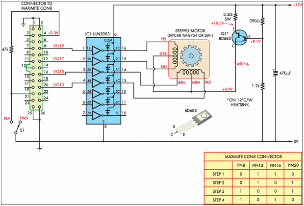
Designing and implementing this circuit was an exciting endeavor. The design of the interface involved learning how to control a device from a computer. A parallel port cable was utilized for this purpose, enabling instant control of the stepper...