
Rotate a stepper motor using a computer

The circuit described involves the use of a parallel port interface to control a stepper motor. The parallel port serves as a communication interface between the computer and the stepper motor driver circuit. In this setup, the computer sends control signals through the parallel port, which are then interpreted by the driver circuit to manage the stepper motor's movement.
The design of the circuit typically includes a microcontroller or a dedicated stepper motor driver IC that receives the signals from the parallel port. The driver IC translates these signals into appropriate voltage levels and current requirements to energize the motor coils sequentially, allowing for precise control of the motor's rotation and position.
Connections in the circuit would include the parallel port pins connected to the input pins of the driver IC. The stepper motor itself is connected to the output pins of the driver, which are responsible for energizing the motor coils in the correct order. Power supply considerations are also critical, as the stepper motor often requires a higher voltage and current than what the parallel port can provide. An external power supply is usually incorporated to meet these requirements.
In addition, it is essential to include protective components such as diodes to prevent back EMF generated by the motor from damaging the driver circuit. Proper grounding and signal integrity measures should also be implemented to ensure reliable operation.
Overall, this circuit exemplifies the principles of digital communication, motor control, and interfacing between a computer and external hardware, demonstrating a successful application of electronics in a practical scenario.Designing and implementing this circuit was really very exciting for us. When designing the interface, we learn things of controlling a device from a computer. We use parallelport cable for this purpose and instantly controlled the rotation of the steppermotor. Since, our designed circuit works properly, so it can be said that we have completed ou r experiment successfully. 🔗 External reference
Related Circuits
A DC drive for a universal motor is depicted in the figure below. To provide DC current to the motor, a diode bridge has been integrated around the motor. The motor... The schematic illustrates a DC drive system designed for...
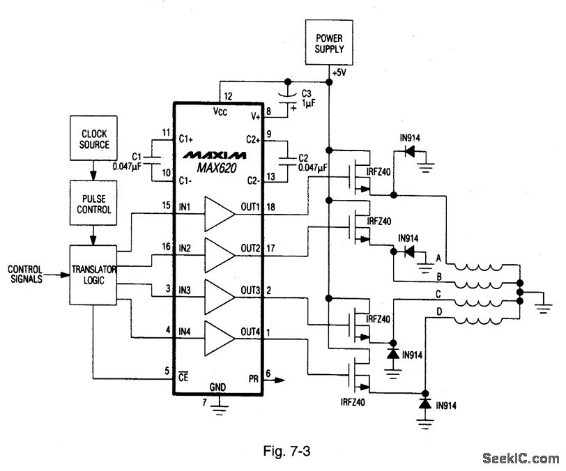
A MAX620 is connected to create a complete stepper motor drive system. TTL/CMOS signals from the logic network are converted to high-side levels that control four N-channel power MOSFETs, which supply current to each of the four phases of...
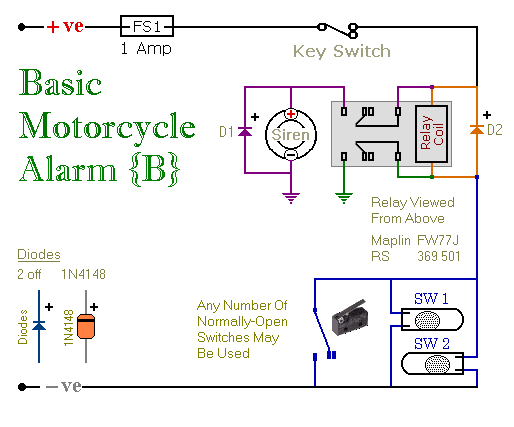
These are two easy-to-build relay-based alarms. They can be used to protect a motorcycle, but they have many additional applications. When using relays with 6-volt coils, they can safeguard a classic bike. Both alarms are compact, with completed boards...
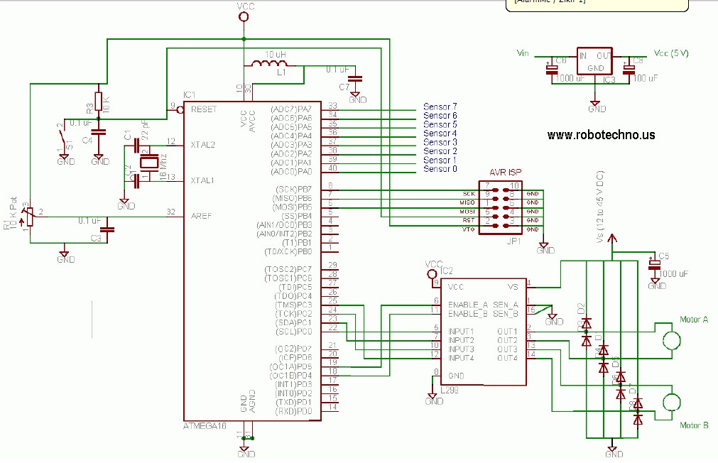
This line follower robot utilizes the following components: eight phototransistor proximity sensors, an ATMega16 microcontroller, an L298 motor driver, and is programmed using the C programming language. The line follower robot is designed to navigate along a designated path by...
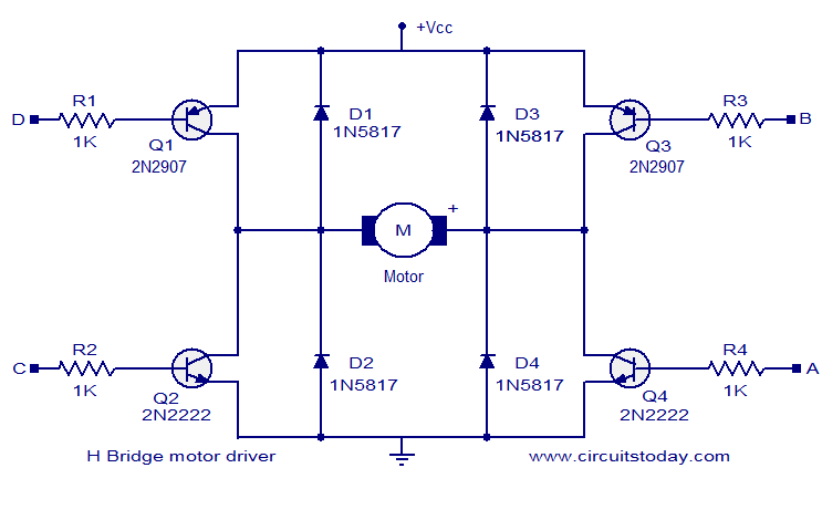
The circuit presented is a simple H-bridge motor driver circuit utilizing commonly available components. An H-bridge is an efficient method for driving motors and is widely used in various electronic projects, particularly in robotics. The circuit illustrated is a...
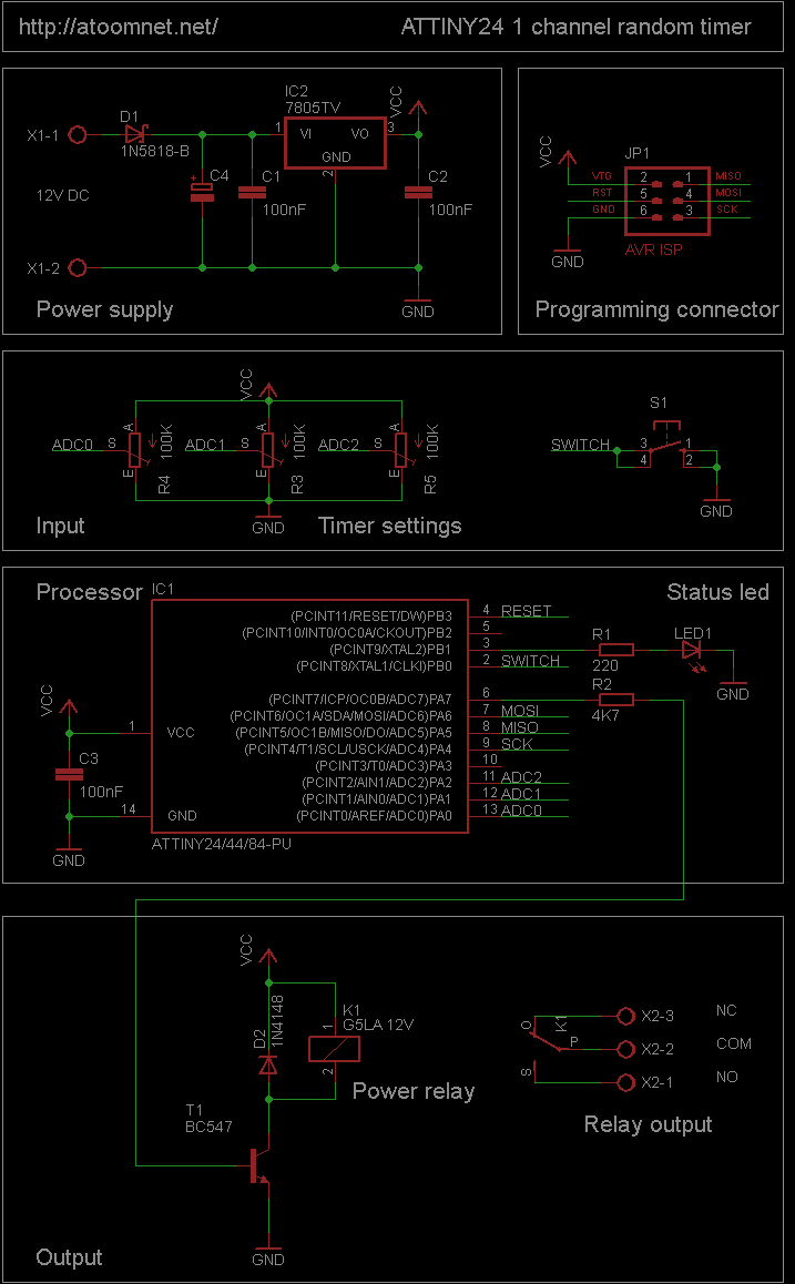
This random timer circuit is based on an Atmel ATTINY24 AVR driving one power relay. It can be used to switch on and off other circuits randomly. For instance, in a model railroad setup, this circuit can activate and...