


Divide-multiply-with-only-one-trim
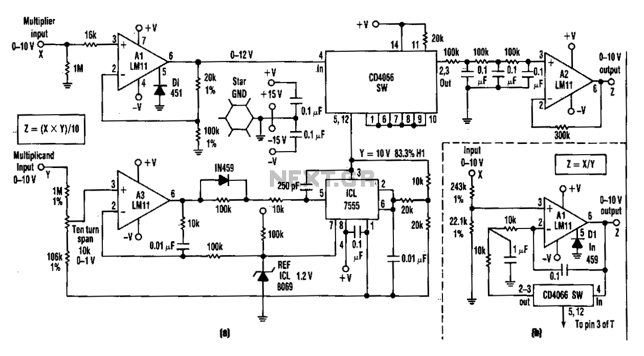
This relatively simple, inexpensive circuit requiring one trimming operation can multiply or divide with a consistentaccuracy of greater than 1 part in 1,000. ...
Electronic-dice
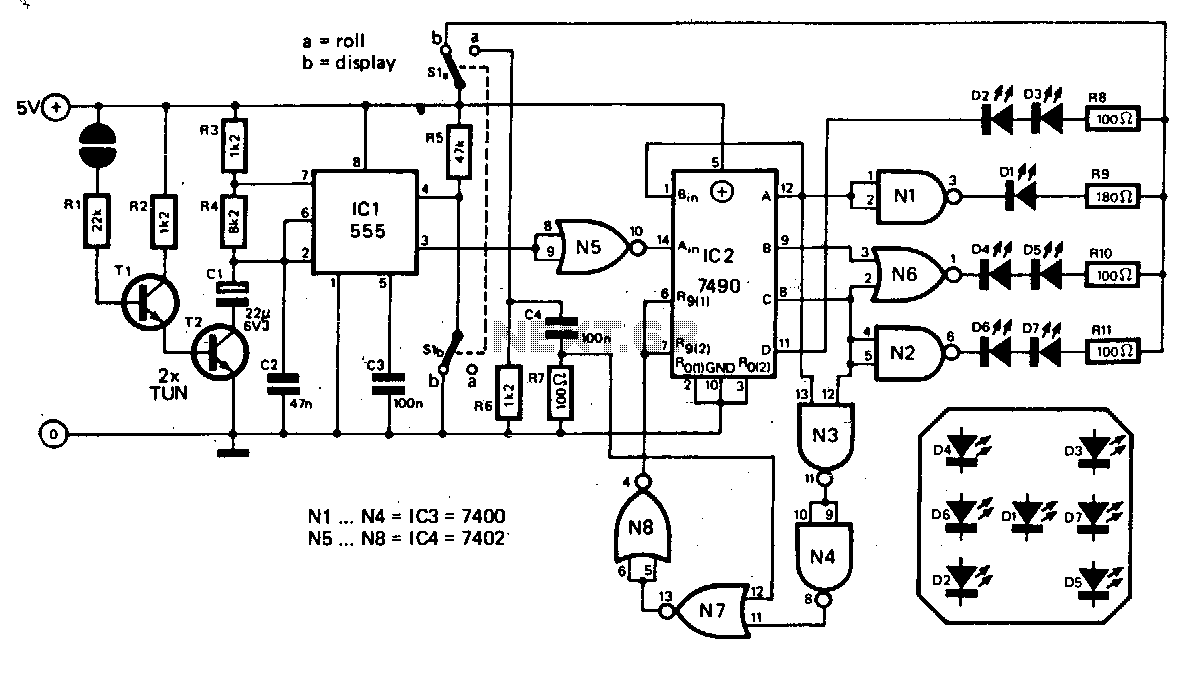
The basic die circuit is given. A 555 timer, ICl, is connected as an astable multivibrator. This feeds clock pulses to divide-by-six counter IC2 tbe outputs of...
Coin-flipper
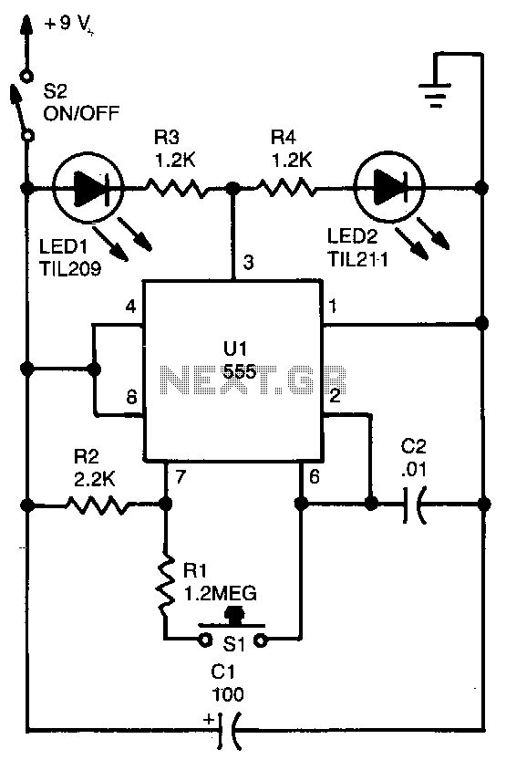
The circuit is basically a 555 astable circuit that divides two LEDs, LEDl and LED2. LED2 is switched on when the output of Ul is high, and LEDl is activated...
Variable-duty-cycle-timer
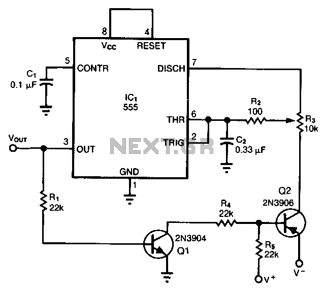
When configured as a free-running multivibrator, a 555 timer provides no more than a 50% duty cycle. By adding two transistors, however, you can obtain a var...
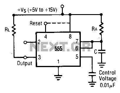
Monostable-operation
In this mode, the timer functions as a one shot. The external capacitor is initially held discharged by a transistor internal to the timer. Applying a negativ...
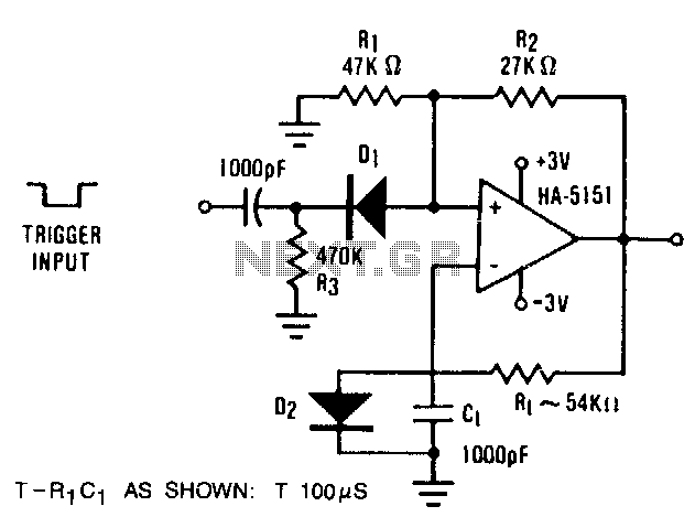
Monostable-multivibrator
The circuit illustrates the usefulness of the HA-5151 as a battery-powered monostable. In this circuit, the ratio is set to .632, which allows the time const...
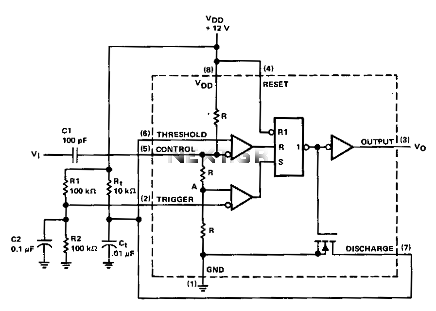
Positive-triggered-monostable
A positive-going trigger pulse can be used to start the timing cycle with the circuit shown. In this design, trigger input pin 2 is biased to 6V (1/z Vvv) by d...
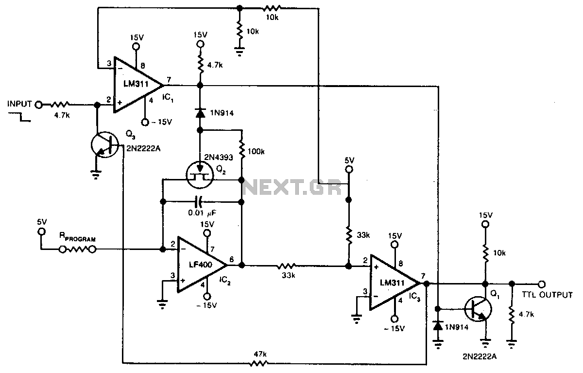
Precision-one-shot
If you need a wide-range, resistor-programmable monostable multivibrator, you can program tbe circuit for pulse widths from 1 JlS to 10s-107:1 range. A high-to...
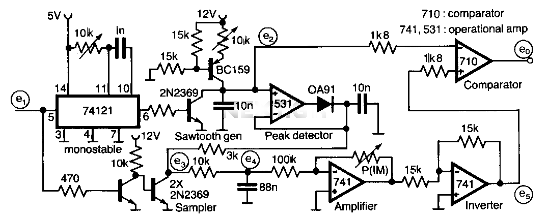
-Pulse-width-multiplier
This circuit for multiplying the width of incoming pulses by a factor greater or less than unity is simple to build and has the feature that the multiplying fa...
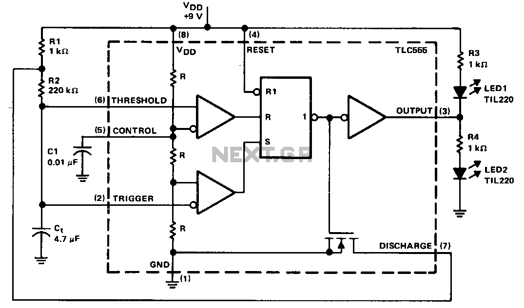
Alternating-led-flasher
The timing components are Rl, R2, and C,. Cl is a bypass capacitor used to reduce the effects of noise. At start-up, the voltage across C, is less than the tri...
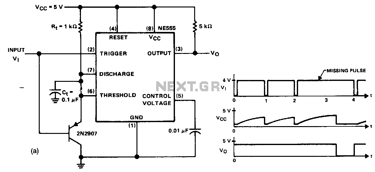
Missing-pulse-detector
This circuit will detect a missing pulse or abnormally long spacing between consecutive pulses in a train of pulses. The timer is connected in the monostable m...
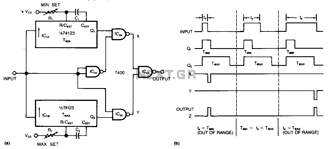
Out-of-bounds-pulse-width-detector
Requiring only two ICs to monitor a train of positive pulses, this circuit produces a single positive output pulse for each input pulse whose duration is eithe...
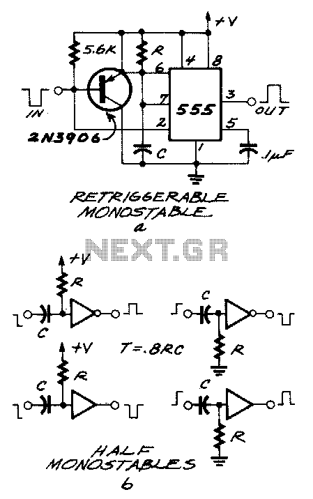
Edge-detector
The 555 is a monostable that wants a negativegoing trigger. If the pulse you"re feeding it with is positive-going, you can run it through an inverter made up...
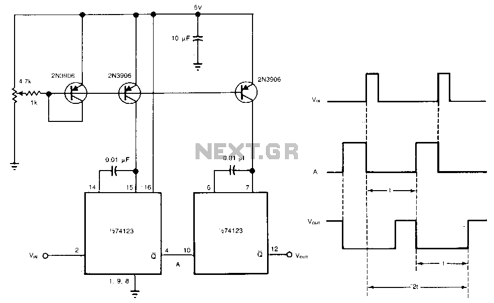
Adjustable-delay
You can obtain well over 360° of phase delay by cascading two monostable multivibrators. In a typical configuration, a single monostable multivibrator is us...
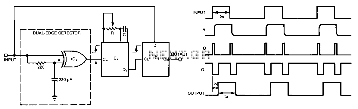
Pulse-delay-with-dual-edge-trigger
A single monostable multivibrator delays a pulse train by a variable amount; nonetheless, this amount can be no less than the minimum allowed pulse width fw�...
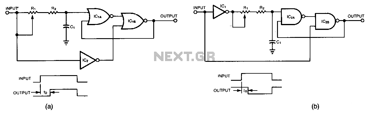
Leading-edge-delay
Circuit (a) lets you delay the leading edge of a positive pulse while leaving the trailing edge almost unaffected. A positive input transition, inverted hy IC2...
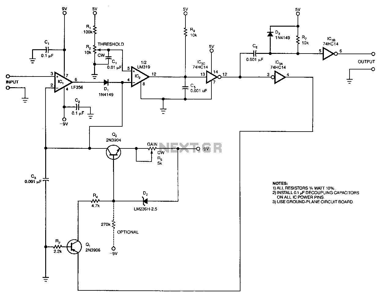
Pulse-height-to-width-converter
The output-pulse width from the circuit is a linear function of the input pulse"s height. You can set the circuit"s input threshold to discriminate against low...
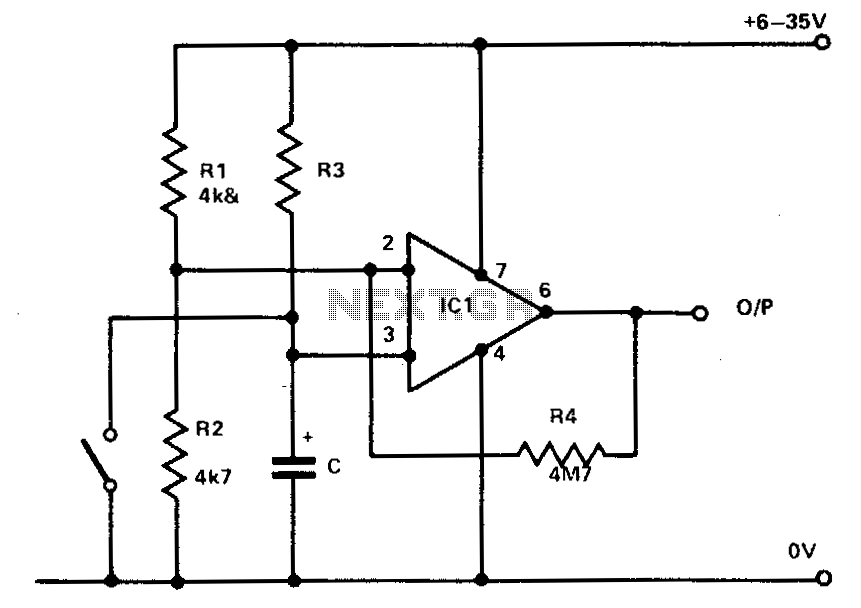
741 Timer
Rl and R2 hold the inverting input at half supply voltage. R4 applies feedback to increase the input impedance at pin 3. Pin 3, the nonin-verting input, is conn...
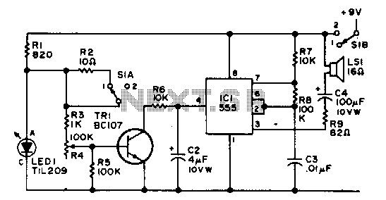
Electronic egg timer
The IC functions as an af multivibrator which is controlled by the external transistor...
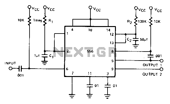
Sequential timing
By utilizing both halves of the dual timer it is possible to obtain sequential timing. By connecting the output of the first half to the input of the second hal...