

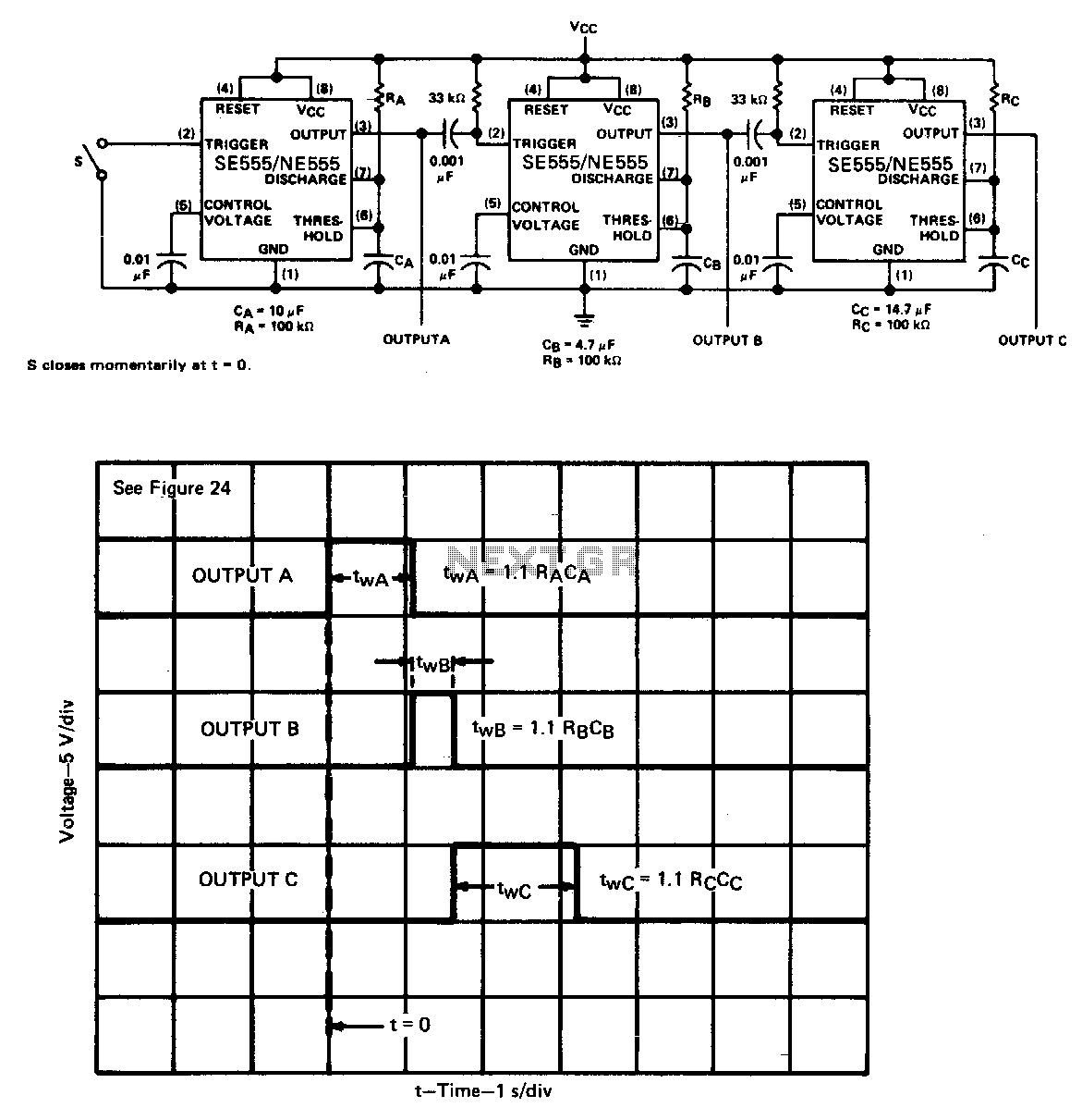

Sequential timer
Many applications, such as computers, require signals for initializing conditions during start-up. Other applications such as test equipment require activation ...
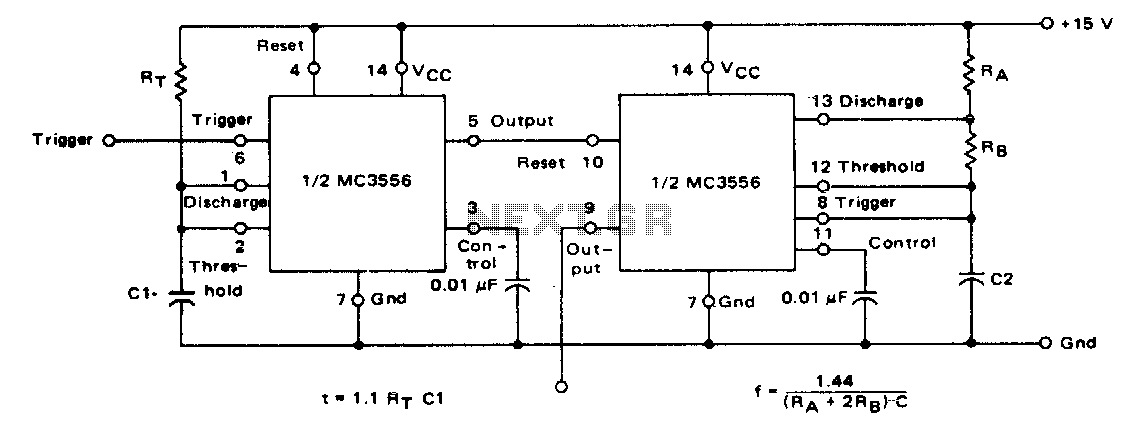
Tone burst generator
The first timer is used as amonostable and determines the tone duration when triggered by a positive pulse at pin 6. The second timer is enabled by the high out...
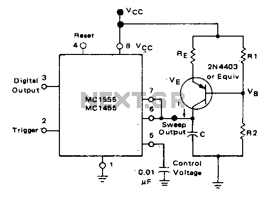
Linear voltage ramp generator
In the monostable mode, the resistor can be replaced by aconstant current source to provide a linear ramp voltage...
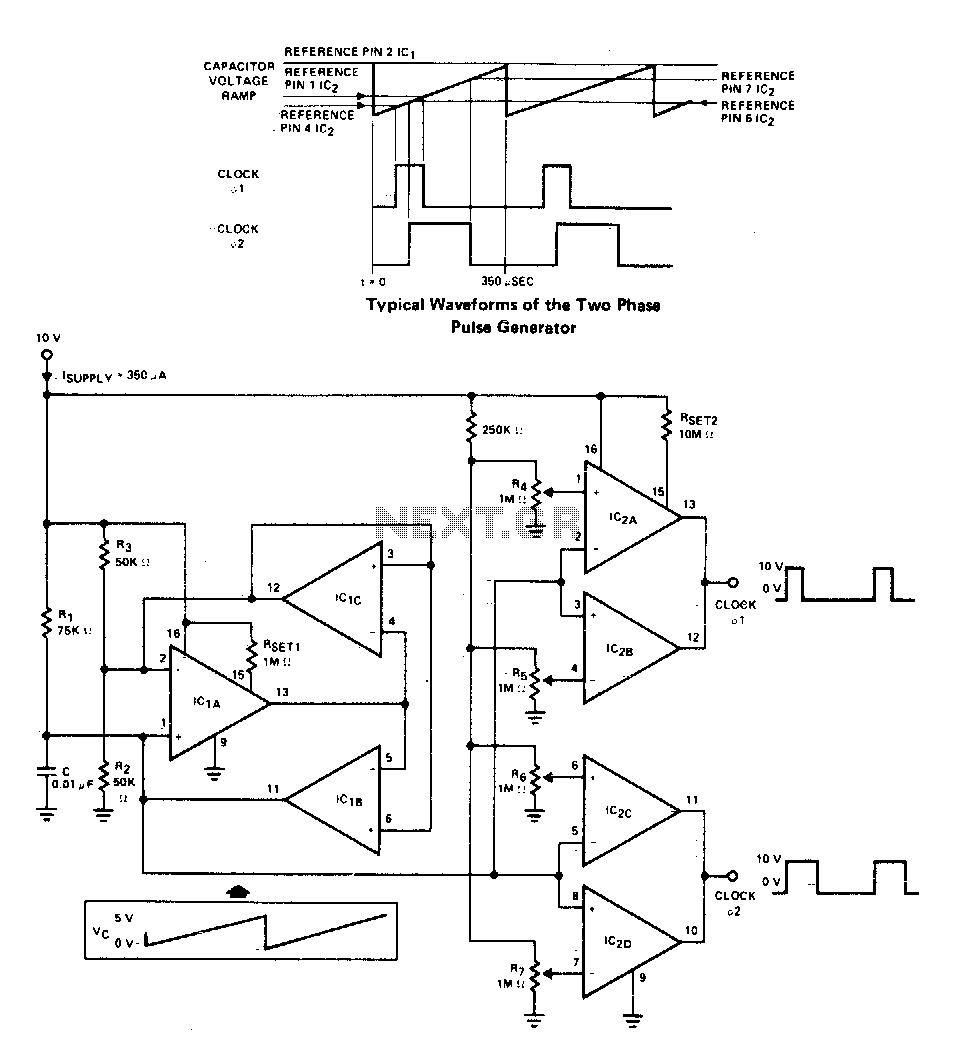
Versatile two-phase pulse generator
Two-phase clock generator uses two L161s to generate pulses of adjustable widths and phase relationships...
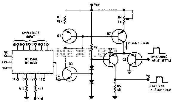
Programmable pulse generator
Fast rise and fall times require the use of high speed switching transistors for the differential pair, Q4 and Q5...
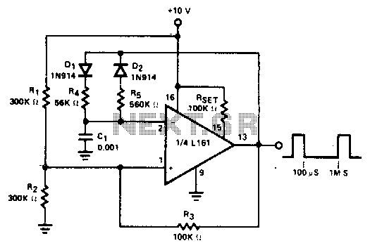
Pulse generator
The duty cycle Of the output pulse is equal to R4/(R4 + R5) x 100%. For duty cycles of less than 50%, Dl can be eliminated and R2 raised...
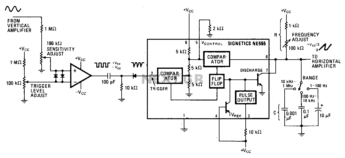
Add-on triggered sweep
The circuit"s input op amp triggers the timer, setting its flip-flop and cutting off its discharge transistor so that capacitor C can charge...
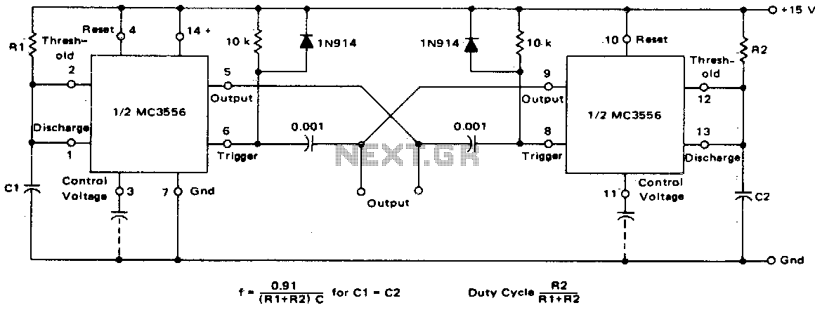
Dual astable multivibrator
This dual astable multivibrator provides versatility not available with single timer circuits. The duty cycle can be adjusted from 5% to 95%. The two outputs pr...
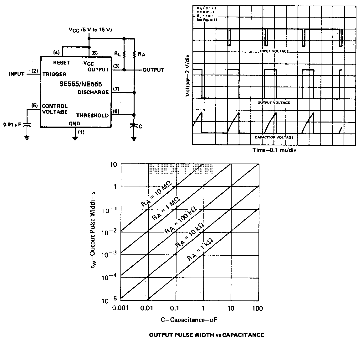
Monostable circuit
If the output is low, application of a negative-going pulse to the trigger input sets the flip-flop (Q goes low), drives the output high, and turns off 1. Capac...
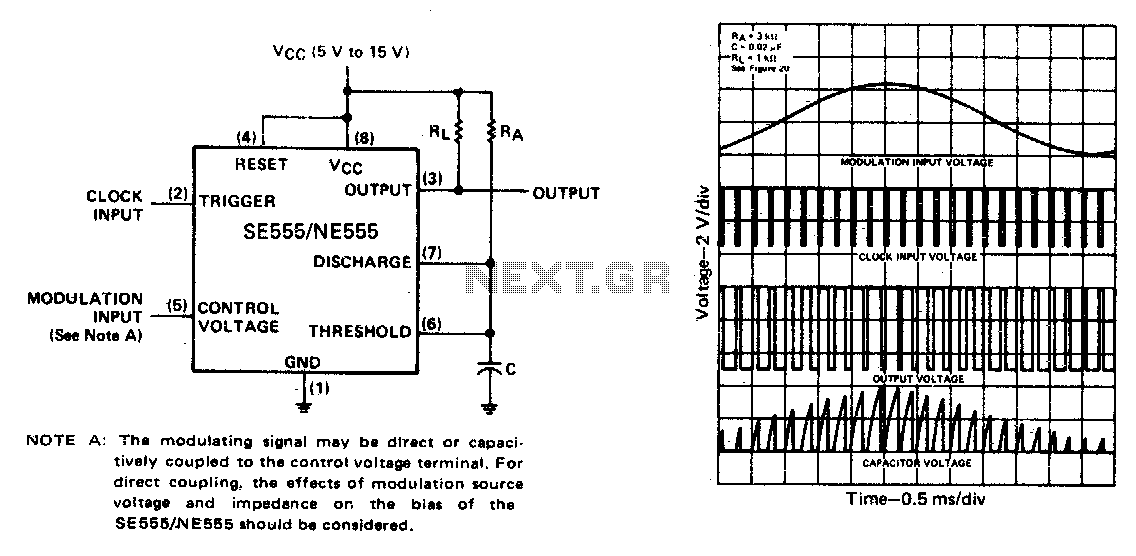
Pulse-width modulator
The monostable circuit is triggered by a continuous input pulse train and the threshold voltage is modulated by a control signal. The resultant effect is a modu...
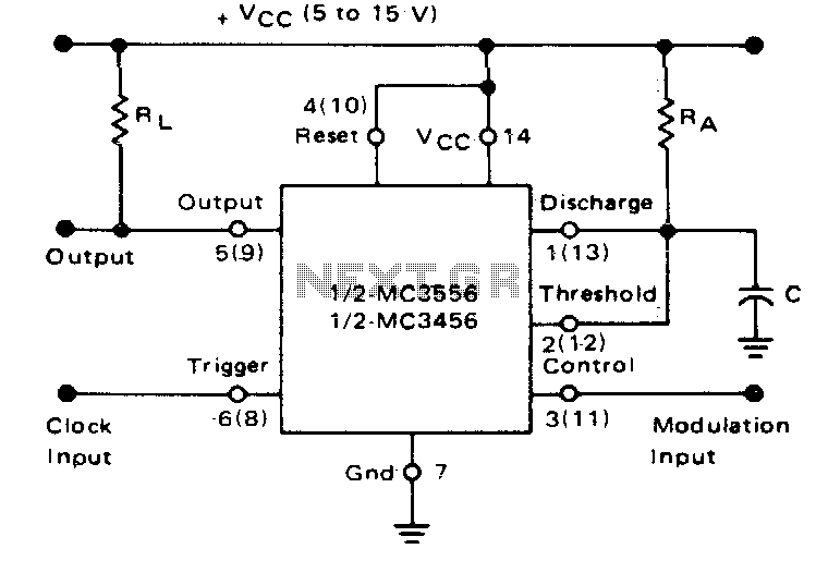
Pulse-width modulator
if the timer is triggered with a continuous pulse train in the monostable mode of operation, the charge time of the capacitor can be varied by changing the cont...
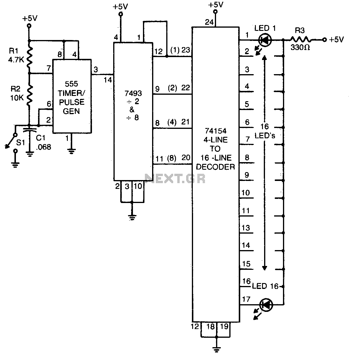
Game roller or chase circuit
The 555 timer produces a rapid series of pulses whenever switch SI is open. These pulses are counted in groups of 16 and converted into binary form by the 7493 ...
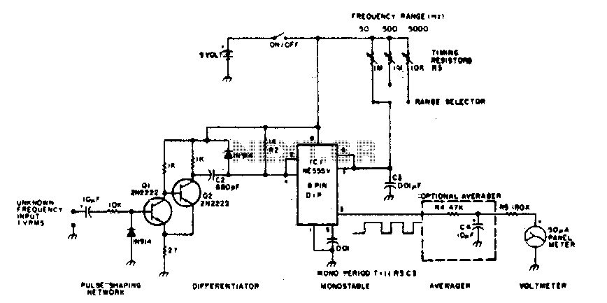
Linear frequency meter
The 555 is used in a monostable multivibrator circuit that puts out a fixed timewidth pulse...

DC flasher with adjustable on and off time
This circuit utilizes a power flip-flop and programmable unijunction (PUT)...
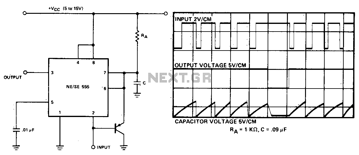
Missing pulse detector
The timing cycle is continuously reset by the input pulse train. A change in frequency, or a missing pulse, allows completion of the timing cycle which causes a...
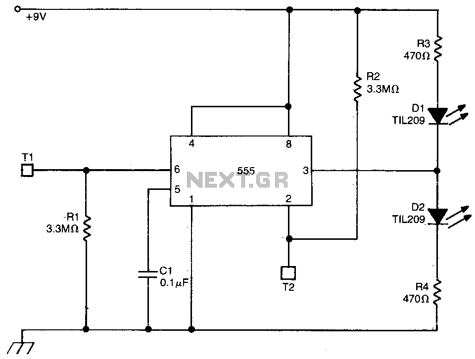
Touch triggered bistable
This circuit uses a 555 timer in the bistable mode. Touching T2 causes the output to go high; D2 conducts and D1 extinguishes. Touching T1 causes the output to ...
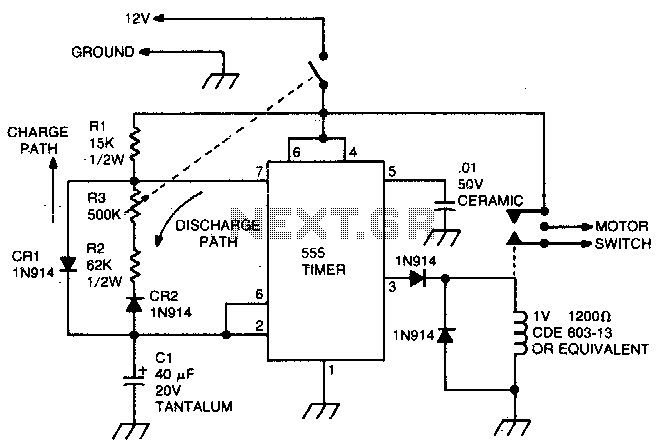
Windshield wiper hesitation control unit
This circuit uses the 555 timer in the asta-ble or oscillatory mode. The length of time the timer is off is a function of the values of CI, R2, and R3. The pote...
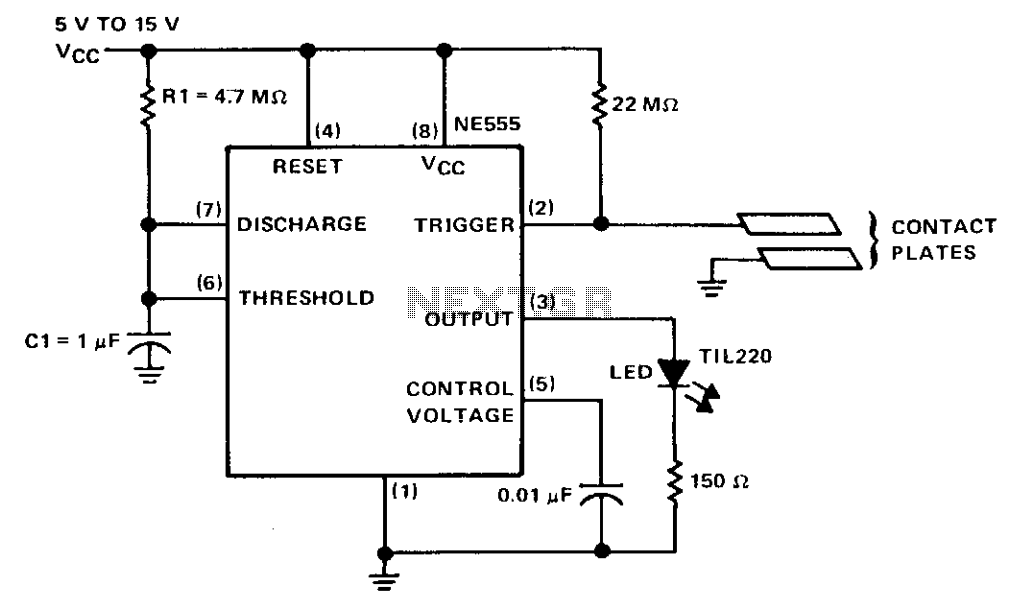
Touch switch
The circuit is basically a NE555 monostable, the only major difference being its method of triggering. The trigger input is biased to a high value by the 22 oh...
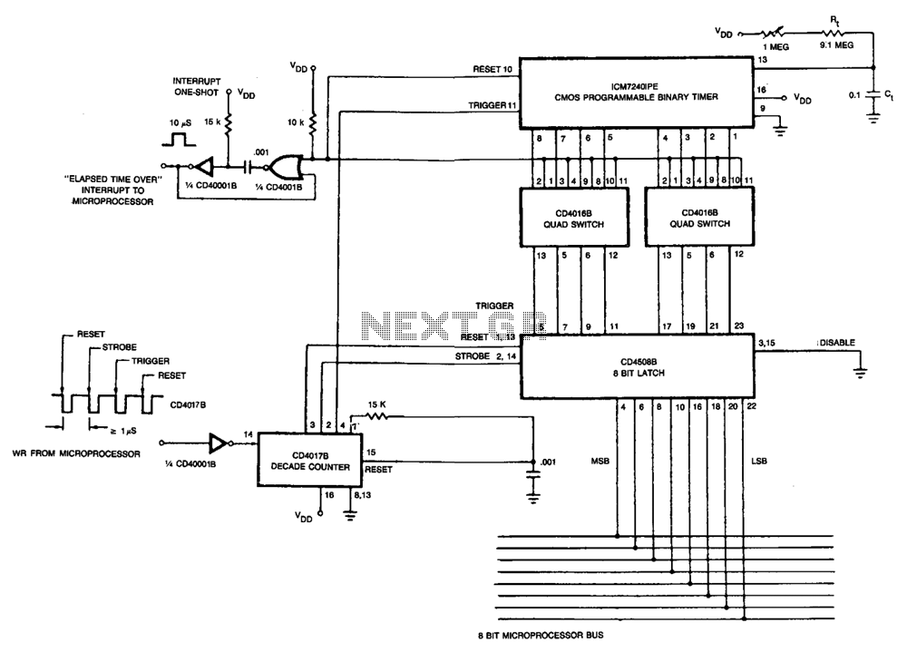
Microprocessor programmable interval timer
The microprocessor sends out an 8-bit binary code on its 8-bit I/O bus (the binary value needed to program the ICM7240), followed by four WRITE pulses into the ...

556 controls temperature and liquid level
One-half of a 556 dual timer monitors the temperature of a liquid bath, controlling a heating element that maintains temperature within ±2°C over a 32°...