
transistors How does this circuit diagram work
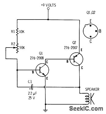
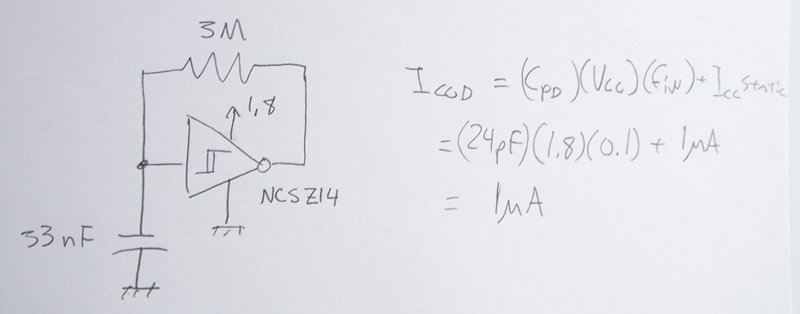
In this circuit, resistor R2 is strategically placed in series with capacitor C1 to regulate the charging rate of C1. The time constant of the RC circuit, defined as τ = R2 × C1, determines how quickly C1 charges to approximately 63% of the supply voltage. Once the voltage across C1 reaches a predetermined threshold, it activates the base of transistor Q1. This transistor, in turn, drives transistor Q2, allowing current to flow through the load, producing the desired 9-volt output.
The interaction between the capacitor and the transistors is crucial for the operation of this circuit. Capacitor C1 functions as a timing element, storing energy and releasing it when the voltage surpasses the trigger point for Q1. The discharge occurs rapidly once the threshold is crossed, effectively transitioning from charging to discharging. This transition is facilitated by the inherent characteristics of the transistors, which allow for rapid switching.
The clicking sound produced is a result of the sudden release of energy stored in C1. The frequency of this sound is influenced by the values of R2 and C1, as they dictate the charging and discharging cycles. Understanding the precise moment when C1 discharges and the factors that contribute to the cessation of charging can be explored further by analyzing the circuit’s feedback mechanisms and the characteristics of the transistors involved.
In summary, the circuit's functionality hinges on the interplay between R2, C1, Q1, and Q2. The design effectively utilizes the properties of capacitors and transistors to create a timing mechanism that produces audible output, illustrating a fundamental principle in electronic circuit design.R2 controls how fast C1 charges, and I know that at a certain point C1 will trigger Q1 and Q2 to release the 9 volts (see 2). This 9 volt burst creates the clicking sound. How does the capacitor discharge I imagine that the capacitor will slowly charge up to a point, then let it out (presumably to Q1).
When does it let out Why does it stop it`s "charging" routine to discharge 🔗 External reference
Related Circuits
There are two types of solar automatic tracking controllers. One type utilizes a Schmitt trigger light control, which consists of a light sensor and a Schmitt trigger or monostable trigger. The second type employs two light sensors and two...
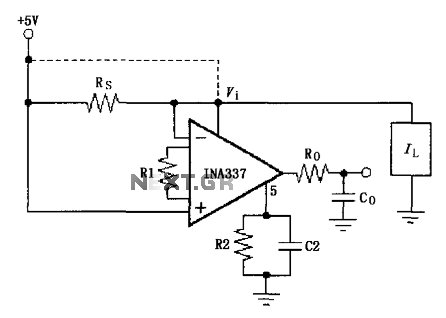
The INA337 circuit, as illustrated, is part of a load current measuring shunt circuit. It generates a voltage drop across the sampling resistor Rs, which is connected in series between the power source and the load. The load current...
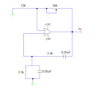
An operational amplifier-based sine wave generator circuit, commonly known as a Wien bridge oscillator, is recognized for its simplicity and stability. The Wien bridge oscillator connects the Wien bridge circuit between the amplifier's input and output terminals. The bridge...

This electronic circuit, based on the CD4017 and logic gates, activates a relay when four keys are pressed in the correct sequence, returning to the initial state afterward. The circuit utilizes the CD4017 decade counter, which is designed to count...
Gyrators are utilized in DC holding circuits, commonly found in Data Access Arrangements (DAAs). DAAs generally employ dry transformers that cannot handle DC current and include a DC blocking capacitor. When the telephone goes off-hook, it is necessary to...
The power supply varies, and the circuit must operate at under 10 µA of current (excluding the capacitor charging). It triggers a Silicon Controlled Rectifier (SCR) every 10 to 30 seconds as long as the power supply is above...