
Electronic Key Circuit

The circuit utilizes the CD4017 decade counter, which is designed to count up to ten and can be configured to detect specific sequences. Four push-button switches are connected to the input of the CD4017, each corresponding to a unique output pin. The logic gates are employed to ensure that the sequence of button presses is validated before activating the relay.
When the first button is pressed, the CD4017 advances to the first output. If the second button is pressed next, the counter will move to the second output, and this continues until all four buttons are pressed in the correct order. If the sequence is completed successfully, a logic high signal is sent to the relay control circuit, energizing the relay and allowing it to switch on the connected load.
In addition to the main components, the circuit may include debounce circuitry to prevent false triggering from mechanical vibrations when the buttons are pressed. This can be achieved using additional logic gates or capacitors in conjunction with resistors. The relay itself can be of various types, depending on the load requirements, and should be selected based on the voltage and current specifications of the intended application.
Finally, once the relay is activated, the circuit will remain in this state until the sequence is interrupted or reset, at which point it will return to the initial state, ready for a new sequence of inputs. This design emphasizes reliability and accuracy in sequence detection, making it suitable for applications in security systems, automation, or interactive control panels.Based on CD4017 and logic gates this electronic circuit switches on a relay if you press four keys in the correct sequence, and backs to the start conditio.. 🔗 External reference
Related Circuits
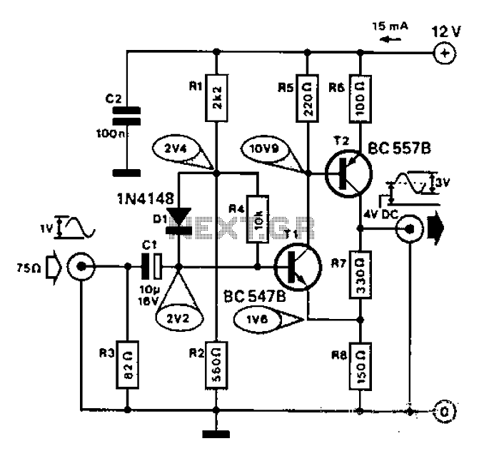
Commonly used for cameras or computers with black and white television connections, the amplifier has a gain of 3 and a bandwidth of 10 MHz. The described circuit is an amplifier designed for applications involving cameras or computers that interface...
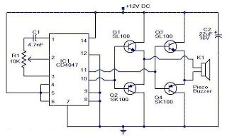
This is a small circuit designed as an insect repellent, targeting mosquitoes and birds by producing high-frequency audio signals. These signals interfere with the hearing of insects, making it unbearable for them, causing them to flee. The operation of...
The performance indices of the telecontrol receiving decoding circuit are as follows: radio frequency (f) = 27 MHz, audio frequency (f) = 5.5 kHz, 100% modulation in square-wave form; radio frequency deviation is ±600 Hz, and the frequency shift...

This circuit is used for a Digital Radar Speedometer. It allows for the measurement of the speed of any moving object, particularly vehicles such as cars. The speed is displayed in kilometers per hour (KPH) with a three-digit display....
The concept for this crystal tester circuit originated from the necessity to evaluate a large quantity of oscillator crystals that were not in use within a hobby box. Testing each crystal individually without the proper equipment would have been...
The circuit was originally available in kit form from a surplus supplier, but it is likely more widely accessible now. It introduces innovative concepts such as utilizing a 555 timer as a pulse width modulator (PWM) and employing serial/parallel...
Warning: include(partials/cookie-banner.php): Failed to open stream: Permission denied in /var/www/html/nextgr/view-circuit.php on line 713
Warning: include(): Failed opening 'partials/cookie-banner.php' for inclusion (include_path='.:/usr/share/php') in /var/www/html/nextgr/view-circuit.php on line 713