
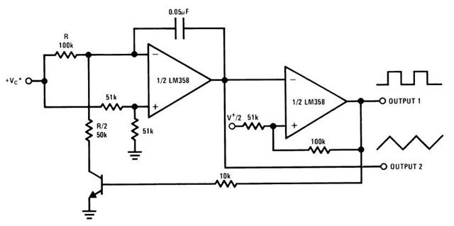
vco circuit diagram
No description available.
Related Circuits
This circuit is designed to indicate when room noise exceeds a predetermined threshold, utilizing a flashing LED to signal this condition. Three fixed noise levels are selectable: 50 dB, 70 dB, and 85 dB. The circuit employs two operational...
The circuit consists of a lag comparator with amplifier A1 and an inverting integrator A2. The charging and discharging time constant is determined by the integral resistors (R1 + RP1) and the capacitor C1. Diodes VD1 to VD5 form...
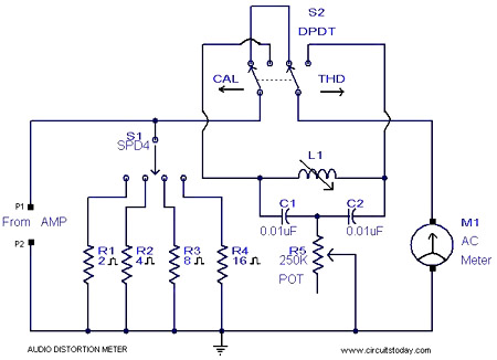
This is a simple 1 kHz audio distortion meter designed to measure the Total Harmonic Distortion (THD) on any load at any output power. The circuit allows for the selection of load impedances of 2, 4, 8, or 16...
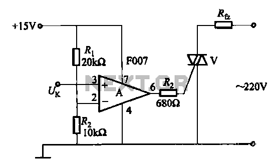
A transistor optocoupler interface circuit, as described in section 15.1.6, has been implemented. This circuit serves as a transistor interface with other circuits. The transistor optocoupler interface circuit utilizes a light-emitting diode (LED) and a phototransistor to achieve electrical isolation...
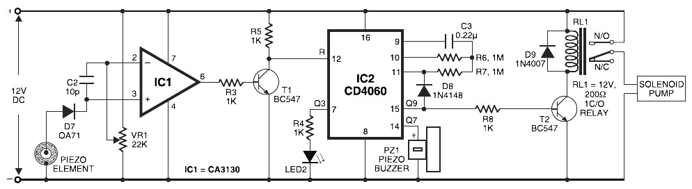
Pyroelectric Fire Alarm System Diagram. The front end of the circuit contains a sensitive signal amplifier constructed close to IC1 (CA3130). It delivers a high output when the temperature near the piezo component raises. IC CA3130 is a CMOS...
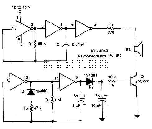
A resistor R1, capacitor C1, and two converters create a square wave generator that produces a fundamental tone. This generator is followed by an inverter that functions as both a buffer and a driver for the system. Resistor R2,...