
Thyristor interface circuit operational amplifier
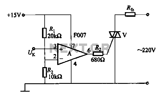
The transistor optocoupler interface circuit utilizes a light-emitting diode (LED) and a phototransistor to achieve electrical isolation between different parts of a system while allowing signal transmission. The LED emits light when current flows through it, and this light is detected by the phototransistor, which then allows current to flow in its circuit, effectively transferring the signal.
In this implementation, the circuit typically consists of an input stage that includes a resistor connected to the LED, which limits the current to a safe level. The LED is connected in series with the input signal source, ensuring that when the input signal is high, the LED turns on, emitting light. The phototransistor is positioned in proximity to the LED, with its collector and emitter configured to control the output circuit.
The output side may include additional components such as pull-up resistors to ensure proper voltage levels when the phototransistor is in the off state. This arrangement helps maintain the integrity of the signal and prevents noise from affecting the output.
The transistor interface circuit is particularly useful in applications where electrical isolation is necessary, such as in power electronics, microcontroller interfacing, and communication systems. It provides a reliable means of interfacing between different voltage levels and protecting sensitive components from high voltages or spikes that may occur in the system.
Careful selection of the LED and phototransistor parameters, including their forward current, reverse voltage, and switching speed, is crucial to ensure optimal performance of the optocoupler circuit in its intended application.Transistor optocouplers interface circuit as described in 15.1.6 has been. Transistor interface circuit with other circuit
Related Circuits
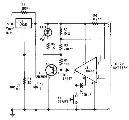
The LM350 car battery charger circuit is a high-performance device designed to efficiently charge gelled lead-acid batteries and automatically terminate the charging process once the battery reaches full charge. This circuit provides a charging current of 2A when the...
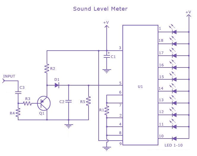
This is a single-chip sound level meter that can be used to display the sound level of an amplifier or simply the sound level from a microphone. The core component of the circuit is the IC LM3915 Audio Level...

This design outlines a high impedance DC voltmeter circuit utilizing the uA741 integrated circuit (IC). The uA741 is configured as a non-inverting DC amplifier. The circuit incorporates negative feedback through a DC meter that requires 1 mA for full-scale...
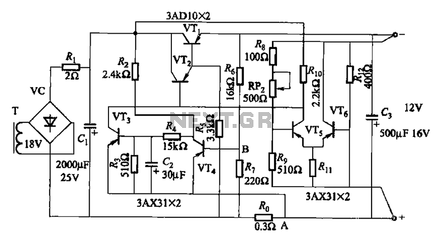
The circuit features a current protection mechanism utilizing transistors VTa, VT4, and a sense resistor Ro. When an overcurrent or short-circuit fault occurs, the power supply cannot resume normal operation because the conduction condition of VT3 remains unchanged, resulting...
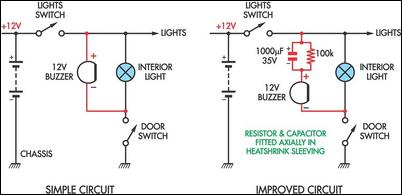
Two headlight reminder circuits are designed for easy installation and operation based on the KISS (Keep It Simple Stupid) principle. The basic circuit consists of a 12V piezo buzzer connected between the lights circuit and a door switch. The...

This schematic outlines a straightforward electronic project for designing a water level indicator circuit. It employs a 7-segment display to represent water levels in a tank as low, half, and full, indicated by the letters L, H, and F,...