
Clap-Controlled Switch
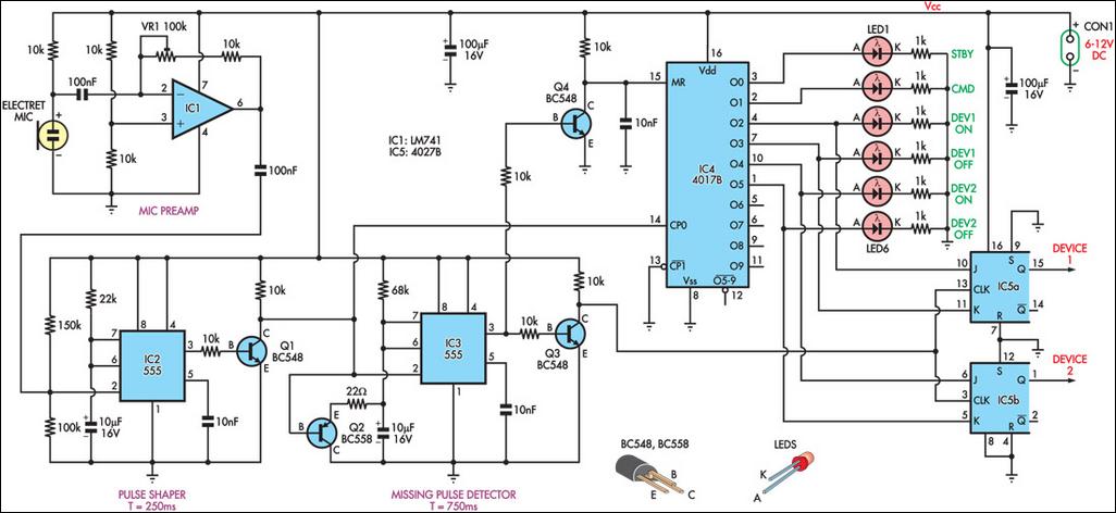
The circuit operates by utilizing an electret microphone to detect sound, which is then amplified by the 741 op-amp. The inverting amplifier configuration allows for sensitivity adjustments, enabling the circuit to effectively respond to varying sound levels. The pulse-shaping stage, implemented with a 555 timer in monostable mode, ensures that only significant sound events (claps) trigger the subsequent logic. The missing-pulse detector further enhances the circuit's responsiveness by allowing it to ignore brief intervals of silence, thus maintaining functionality during rapid sequences of claps.
The 4017 decade counter provides a straightforward method for counting the number of claps, with visual feedback through LEDs that indicate the current state of the circuit. The use of J-K flip-flops allows for more complex command generation, enabling the circuit to control multiple devices based on the count of handclaps received. The design also includes safety features, such as the delay in resetting the counter to prevent premature resets that could disrupt normal operation.
Overall, this circuit exemplifies a practical application of audio detection and digital logic, offering a user-friendly interface for controlling multiple devices through simple hand gestures. By integrating various components like operational amplifiers, timers, and counters, the circuit achieves a balance of sensitivity, responsiveness, and expandability, making it suitable for a range of electronic control applications.This circuit can switch two or more devices on and off in response to a series of rapid handclaps. The claps are picked up by an electret microphone and amplified by a 741 op amp (IC1). IC1 is configured as an inverting amplifier, with its gain and hence the sensitivity of the circuit adjustable via trimpot VR1. Its output is then fed into a pulse -shaping stage based on a 555 timer (IC2). The 555 is configured as a monostable multivibrator, with its trigger input (pin 2) normally biased to about 0. 4VCC by the 150kW and 100kW resistors. When a loud enough sound is detected, pin 2 will be pulled below 1/3VCC, triggering the monostable. The output (pin 3) will immediately swing high, causing transistor Q1 to conduct. The result is a 250ms low-going pulse at the collector of Q1. The output from the pulse-shaper stage is fed into a missing-pulse detector based on a second 555 timer (IC3), which is also configured as a monostable multivibrator.
However, this monostable circuit differs from the first because it includes a "retrigger" function. Retriggering is made possible by transistor Q2, which acts to rapidly discharge the 10mF timing capacitor should a pulse arrive when the timer is already running. This means that once triggered, IC3`s output will remain high as long as additional trigger pulses are received within its set timing period.
Pulses from Q1`s collector are also applied to the clock (CP0) input of a 4017 decade counter (IC4). In the initial state, output 0 (pin 3) of the counter is high, illuminating LED1. The first pulse advances the count and lights LED2, indicating that the circuit is active and ready to receive a handclap "command". Each time another pulse (clap) is received before IC3`s timing period expires, the process repeats, incrementing the counter by one.
When IC3`s timing period is allowed to expire (ie, no claps have been detected for 750ms), the output (pin 3) will go low, turning off transistors Q3 & Q4. The rising voltage on the collector of transistor Q3 clocks two J-K flipflops (IC5a & IC5b), with the result at their Q outputs dependent on the state of the O2-O5 counter outputs.
Considering all the possible logic states of a J-K flipflop, the "commands" will therefore be: Finally, the rising voltage on the collector of Q4 resets the counter, ready for the next clap sequence. Note the addition of a 10nF capacitor between the reset input (pin 15) and ground, which in conjunction with the 10kW resistor adds a short delay to the reset signal.
This ensures that the counter is not reset until after the J-K flipflops have been clocked. If desired, the circuit could easily be expanded by adding more flip-flops and counters. 🔗 External reference
Related Circuits
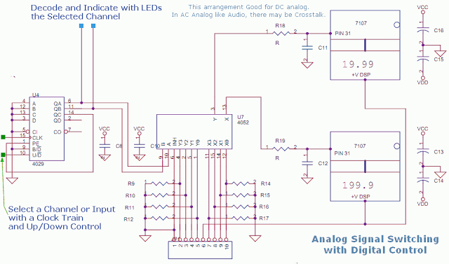
This circuit utilizes a 4052 as a DC Analog Multiplexer. The inputs to this multiplexer must originate from low-impedance output operational amplifiers (OpAmps). The resistors depicted are unnecessary once the signal conditioning OpAmps are connected. However, 100K resistors can...
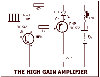
Our circuit is amplifying the current flowing through your finger (when it touches the touch plate) 10,000 times and this is sufficient to illuminate the LED. The current flowing through your finger (when touching the touch plate) is only...
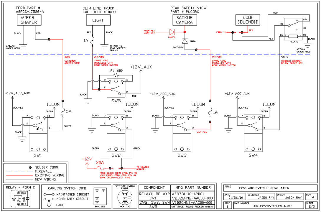
A +12V switched wire was routed back to the camera wiring and connected at the same point as the reverse lights. This configuration allows either the reverse lights or the switch to activate the camera. The critical component in...
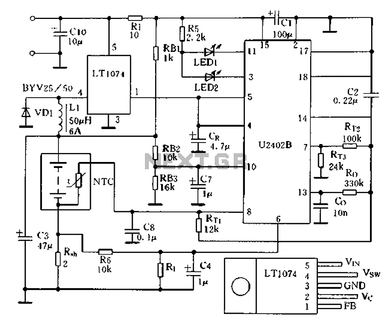
Charging circuit from the DC power supply switching power supply control The charging circuit described is designed to operate with a DC power supply, utilizing a switching power supply control mechanism. This type of circuit is commonly employed in applications...
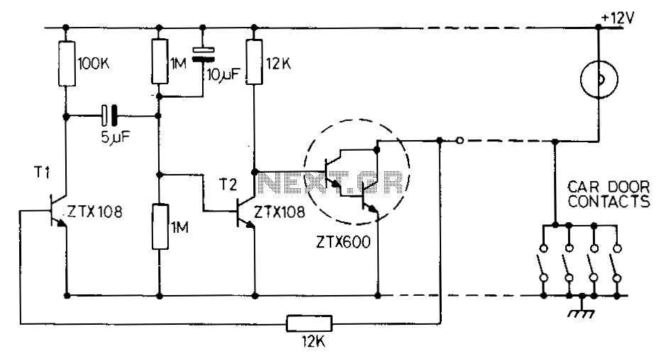
This circuit maintains the internal light for approximately one minute after the car doors are closed. When the door contacts open, a positive voltage pulse is applied to the base of transistor T1. This action activates T1, which in...
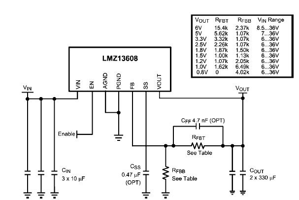
A simple, high-efficiency switching power supply circuit can be designed using the LMZ13608 8A regulator. This regulator offers very high efficiency and requires few external components. It supports a wide input voltage range of 6 to 36 volts and...