
Clock Oscillator BasicCircuit from Sirius microSystem
The clock oscillator circuit is a fundamental component in various electronic systems, providing a stable clock signal for timing applications. The design typically includes a few essential components: an oscillator, a capacitor, and a resistor. The oscillator can be a transistor-based configuration or an integrated circuit (IC) like the 555 timer.
In designing the circuit, the selection of the oscillator type is crucial. For low-frequency applications, a simple RC (resistor-capacitor) oscillator may suffice, while higher frequencies might require more sophisticated arrangements, such as a crystal oscillator, which offers enhanced stability and precision.
The capacitor in the circuit plays a significant role in determining the frequency of oscillation. The value of the capacitor, in conjunction with the resistor, sets the time constant, which directly influences the oscillation frequency. The relationship can be expressed using the formula f = 1/(2πRC), where f is the frequency, R is the resistance, and C is the capacitance.
Additionally, the power supply voltage must be carefully considered to ensure that all components operate within their specified limits. Proper decoupling capacitors may also be added to filter out noise and ensure stable operation.
The output of the clock oscillator can be used to drive other digital circuits, such as flip-flops, counters, or microcontrollers, providing them with a reliable timing source. The design should also include provisions for adjusting the output frequency, which can be achieved through variable resistors or capacitors, depending on the application requirements.
Overall, the clock oscillator circuit is essential for synchronizing operations in digital electronics, and careful attention to component selection and circuit design will ensure optimal performance.The following file contains detail info about design of Clock Oscillator Basic Circuit Diagram. Included in this file information about: selecting the.. 🔗 External reference
Related Circuits
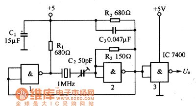
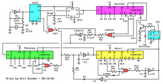
The oscillator circuit consists of a 1MHz quartz crystal resonator and a NAND gate, with the output buffer stage provided by NAND gate 3. This circuit can be utilized for calibrating standard frequency. The described oscillator circuit operates at a...
This is a programmable alarm timer circuit that uses LEDs to indicate hours and minutes. Twelve LEDs can be arranged in a circle to represent the 12 hours of a clock face, and an additional 12 LEDs can be...
The circuit was designed to create a frequency converter using a crystal oscillator for the conversion of 10 MHz to 1 MHz. It incorporates a 7404 hex inverter. The circuit functions as a frequency divider, utilizing a crystal oscillator to...
The following circuit illustrates a Cat and Dog Repellent Timer Circuit Diagram. Features include the capability to maintain a deep cycle battery charged by a solar panel. The Cat and Dog Repellent Timer Circuit is designed to provide a humane...
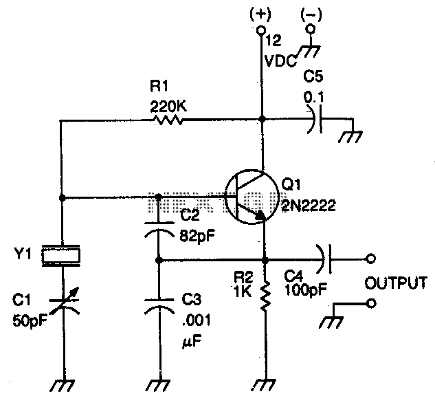
This circuit operates with fundamental-mode crystals in the frequency range of 1 MHz to 20 MHz. Feedback is regulated by the capacitor voltage divider formed by capacitors C2 and C3. The RF voltage across the emitter resistor supplies the...
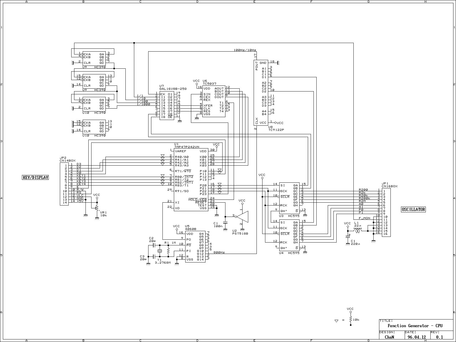
Oscillation frequency 10Hz ~ 20MHz, 6 ranges. Analog output Sine, triangle, square wave (0 ~ 4Vp-p, Zo = 50Ω). TTL Output Clock (Duty: 50% fixed) positive negative pulse (variable pulse width). Operating system Show: oscillation frequency and operating mode...
Warning: include(partials/cookie-banner.php): Failed to open stream: Permission denied in /var/www/html/nextgr/view-circuit.php on line 713
Warning: include(): Failed opening 'partials/cookie-banner.php' for inclusion (include_path='.:/usr/share/php') in /var/www/html/nextgr/view-circuit.php on line 713