
Clap Switch Circuit Project
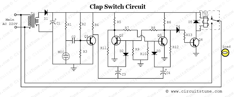
This clap switch circuit is designed to provide a convenient and innovative method for controlling electrical devices using sound. The core components include a condenser microphone that captures the sound of a clap and converts it into an electrical signal, which is crucial for the operation of the entire circuit. The initial amplification stage provided by Q1 ensures that the signal from the microphone is strong enough for further processing.
The bistable multivibrator configuration formed by Q2 and Q3 is essential for creating a toggle effect in response to the clap sound. This configuration allows the circuit to maintain its state until another trigger is received. The flip-flop behavior is particularly useful in applications where a momentary action (the clap) needs to control a persistent state (the on or off state of an appliance).
The relay, driven by Q4, serves as the interface between the low-voltage control circuit and the high-voltage load. This is a critical safety feature, as it allows the user to operate high voltage devices without direct interaction with high voltages. The relay's activation is contingent upon the output from the current amplifier, which ensures that the relay operates reliably and is capable of handling the current requirements of the connected appliances.
In summary, this clap switch circuit exemplifies an effective application of basic electronic components to create an interactive and user-friendly device for controlling electrical appliances through sound, demonstrating principles of amplification, signal processing, and relay operation.This is a simple electronics circuit of clap switch project. If you are a beginner electronics learner, and love to get new project experiment then this is a great circuit for you. This circuit can on/off a 220V electronic device like fan, lamp by the sound of clap. As shown in the circuit a very few number of parts is used including relay, transf ormer, condenser microphone, few transistor, a lamp etc. Lamp is used as a testing device; here another device could be use like fan, calling bell, radio etc. A small microphone (MIC) detects the clap sound and converts into electrical signal. Which is amplified by Q1 (here Q1 used as a common emitter amplifier). Amplified signal goes into the Bistable Multivibrator section made by two transistors Q2 and Q3. When we apply a trigger to the Bistable Multivibrator circuit with a clap sound then, if Q2 is on, Q3 gets switched off.
Thus, the circuit remains stable in a single state continuously. At the moment if we trigger with another clap sound the two states will flip-flop with Q2 switched off and Q3 switched on. The circuit will remain stable continuously until we apply the next trigger. Relay gets triggered from the output of current-amplifier (Q4) which is used to amplify the flip-flop signal.
Relay is kind of electromagnetic switch, which is used to controlling other high voltage (AC) electrical appliance (Load in our circuit) with this low voltage (DC) clap switch. 🔗 External reference
Related Circuits
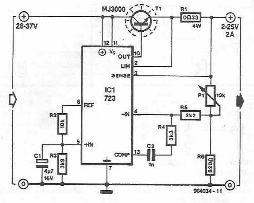
A simple variable power supply circuit can be designed using the LM723 regulator, which provides a maximum current of up to 2A and a variable voltage range between 2 and 25 volts. The LM723 voltage regulator is an integrated circuit...
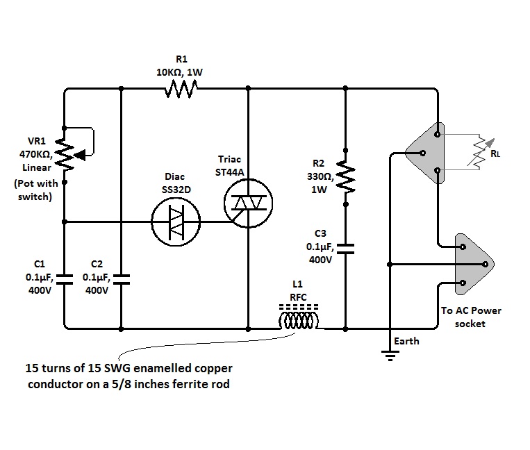
The circuit of a simple triac light dimmer can be used to dim incandescent lamps directly from AC mains. It is easy to construct and requires very few components. A potentiometer is utilized to control the load power or...
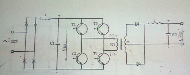
A power supply with frequent energy switching; however, the schematic is incomplete. An additional circuit is needed to control the voltage polarity converter, which consists of four transistors. This circuit generates high-frequency current pulses. Assistance is appreciated to explain...
The LM3886 is an improved version of the LM3875. Key features of the LM3886 include a maximum output power of 68W RMS and 108W peak, with a total harmonic distortion (THD) of 0.03% at 60W. The LM3886 is a high-performance...
This inductance meter serves as an adapter for a digital voltmeter (DVM), enabling the voltmeter to measure the value of inductors. The inductance meter is particularly useful in designing switch mode power supplies, as it often requires hand-winding coils...
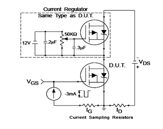
The IRF9540N Gate Charge Test Circuit is illustrated in the diagram below. The IRF9540N is recognized as a rectifier device that employs advanced processing techniques to attain an exceptionally low on-resistance per unit area, as stated in the datasheet....
Warning: include(partials/cookie-banner.php): Failed to open stream: Permission denied in /var/www/html/nextgr/view-circuit.php on line 713
Warning: include(): Failed opening 'partials/cookie-banner.php' for inclusion (include_path='.:/usr/share/php') in /var/www/html/nextgr/view-circuit.php on line 713