
Triac Dimmer Circuit
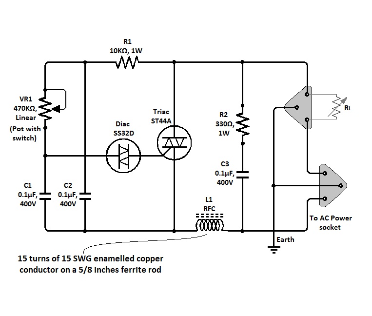
The simple triac light dimmer circuit operates by controlling the phase angle of the AC voltage applied to the load, which in this case is an incandescent lamp or a ceiling fan. The primary components of the circuit include a triac, a diac, a potentiometer, and a few passive components such as resistors and capacitors.
In the circuit, the triac acts as a switch that can turn on and off at specific points in the AC voltage cycle. The diac is used to provide a triggering mechanism for the triac; it remains off until the voltage across it reaches a certain threshold, at which point it conducts and triggers the triac. The potentiometer allows the user to adjust the phase angle at which the triac is triggered, effectively controlling the amount of power delivered to the load.
The circuit is connected directly to the AC mains supply, and safety precautions must be taken during construction and use. It is advisable to use components rated for the appropriate voltage and current levels to prevent overheating and potential failure. Additionally, the circuit should be housed in a suitable enclosure to prevent accidental contact with live components.
When using this dimmer circuit for ceiling fans, the design may need to be adjusted to account for the inductive nature of the fan motor, which can affect the performance of the triac. Proper selection of components and careful tuning of the circuit may be required to achieve optimal results.
Overall, this simple triac light dimmer circuit provides an effective solution for controlling the brightness of incandescent lamps and the speed of ceiling fans with minimal complexity and cost. The circuit of a simple triac light dimmer shown below can be used for dimming incandescent lamps directly from AC mains. The circuit is very easy to construct and uses very few components. The pot is used for controlling the load power or the intensity of the light. The circuit can be also used for controlling ceiling fan speeds. 🔗 External reference
Related Circuits
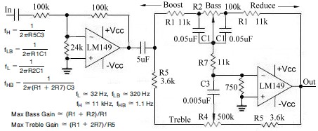
This topic continues from the more general Passive Tone Control circuit, which begins using only passive filters. This circuit follows the previous design, although the component values are different and in an alternate configuration. An audio tone control combines...
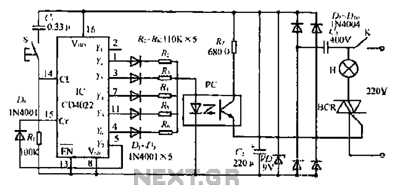
The 1C foot VIII developed a training device, utilizing the trigger terminal CI for a positive input pulse. It concludes by providing a quotient output level. The system involves a commercial electric circuit featuring a buck converter, which limits...
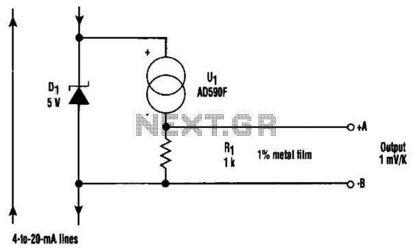
At the core of this circuit is the KTY10 temperature sensor from Siemens. This silicon sensor functions as a temperature-dependent resistor, integrated as one arm of a bridge circuit. A preset potentiometer (P1) is used to balance the bridge...
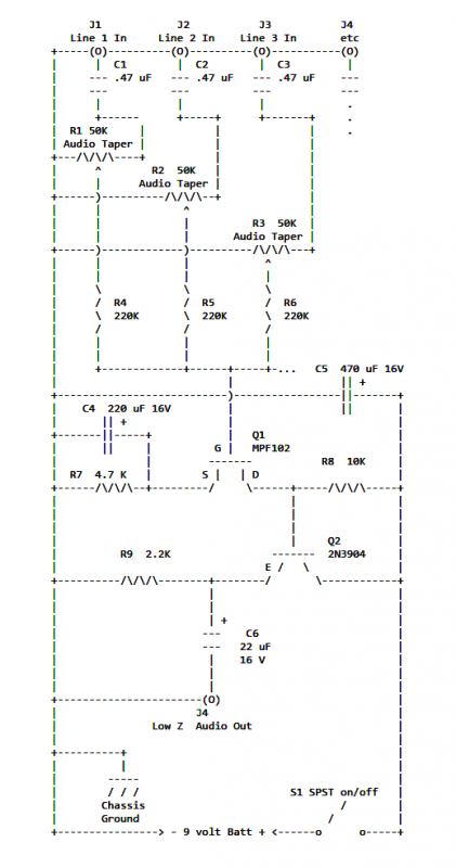
If two of these circuits are made in the same enclosure for stereo, then there can be a single power supply to run both of them. There should be a resistor in series with the incoming 9V+ lead so...
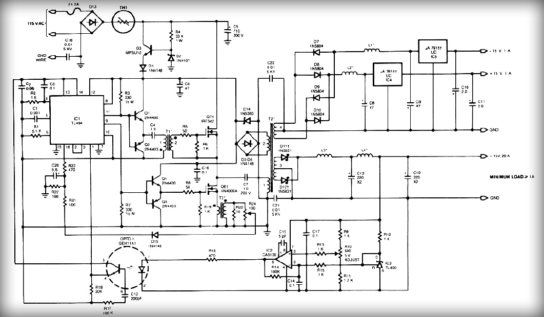
This power supply employs two VN400A 400-Volt MOSFETs arranged in a half-bridge configuration. The outputs provide +5V at 20A and +15V at 1A. Low-current outputs utilize three-terminal regulators, allowing for either 12 Volts or 15 Volts to be achieved...
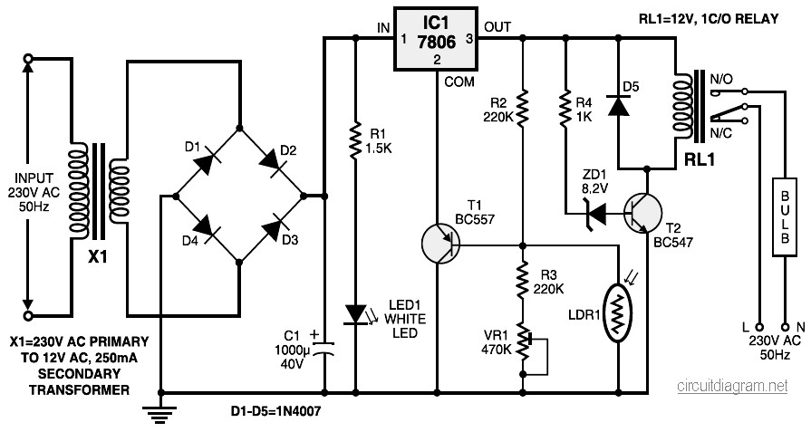
During nighttime, when no light falls on LDR1, it offers a high resistance at the base junction of transistor T1. Consequently, the bias is significantly reduced, and T1 does not conduct. This effectively removes the common terminal of IC1...