
audio stereo channel selector circuit
In this design, the circuit effectively manages audio signal routing from multiple sources, allowing for seamless transitions between channels based on audio presence. The use of analog switches facilitates low distortion in signal integrity, while the adjustable thresholds ensure versatility in various audio environments. The inclusion of visual indicators (LEDs) enhances user interaction by providing real-time feedback on the selected channel. The architecture demonstrates a robust solution for audio management in applications requiring automatic channel selection, such as home theater systems, audio mixing setups, or multi-source audio systems. The ability to manually skip channels adds convenience, making it suitable for dynamic audio environments where user control is essential.This circuit has accouterment for abutting stereo outputs from four altered sources/channels as inputs and alone one of them is selected/connected to the achievement at any one time. When ability accumulation is angry on`, approach A (AR and AL) is selected. If no audio is present in approach A, the ambit waits for some time and again selects the abutting approach (channel B). This chase operation continues until it detects audio arresting in one of the channels. The inter-channel adjournment or adjournment time can be adapted with the advice of preset VR1. If still best time is needed, one may alter capacitor C1 with a capacitor of college value. Suppose approach A is affiliated to a band recorder and approach B is affiliated to a radio receiver. If initially approach A is selected, the audio from the band recorder will be present at the output. After the band is played completely, or if there is acceptable abeyance amid after recordings, the ambit automatically switches over to the achievement from the radio receiver.
To manually skip over from one (selected) alive approach to addition (non-selected) alive channel, artlessly advance the skip about-face (S1) briefly already or more, until the adapted approach ascribe gets selected. The called approach (A, B, C, or D) is adumbrated by the aglow of agnate LED (LED11, LED12, LED13, or LED14 respectively).
IC CD4066 contains four alternation switches. These switches are affiliated to four abstracted channels. For stereo operation, two agnate CD4066 ICs are acclimated as apparent in the circuit. These alternation switches are controlled by IC CD4017 outputs. CD4017 is a 10-bit arena adverse IC. Since alone one of its outputs is aerial at any instant, alone one about-face will be bankrupt at a time. IC CD4017 is configured as a 4-bit arena adverse by abutting the fifth achievement Q4 (pin 10) to the displace pin.
Capacitor C5 in affiliation with resistor R6 forms a power-on-reset ambit for IC2, so that on antecedent switching on` of the ability supply, achievement Q0 (pin 3) is consistently high`. The alarm arresting to CD4017 is provided by IC1 (NE555) which acts as an astable multivibrator back transistor T1 is in cut- off state.
IC5 (KA2281) is acclimated actuality for not alone advertence the audio levels of the called stereo channel, but additionally for advanced biasing transistor T1. As anon as a specific beginning audio akin is detected in a called channel, pin 7 and/or pin 10 of IC5 goes low`.
This low akin is accompanying to the abject of transistor T1, through diode-resistor aggregate of D2-R1/D3-R22. As a result, transistor T1 conducts and causes achievement of IC1 to abide low` (disabled) as continued as the called approach achievement exceeds the preset audio beginning level.
Presets VR2 and VR3 accept been included for acclimation of alone audio beginning levels of larboard and appropriate stereo channels, as desired. Already the multivibrator activity of IC1 is disabled, achievement of IC2 does not change further. Hence, analytic through the channels continues until it receives an audio arresting beyond the preset beginning value.
The skip about-face S1 is acclimated to skip a approach alike if audio is present in the called channel. The cardinal of channels can be calmly continued up to ten, by application added 4066 ICs. 🔗 External reference
Related Circuits
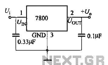
A fixed three-terminal integrated voltage regulator can be directly employed in various electronic devices as a voltage regulator. It features internal protections such as overcurrent protection, thermal protection, and safe operating area protection, making the circuit easy to use,...
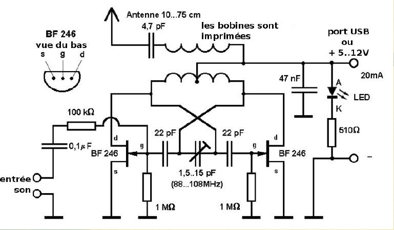
Here is a small FM transmitter circuit designed for desktop or laptop use, allowing users to enjoy movies and music from a distance. This USB-powered FM transmitter connects to a computer or MP3 player and broadcasts on a tape...
The sensor operates on the principle that at high temperatures (200 to 800 °F), the temperature of the sensor varies with the thermal conductivity of gas, leading to changes in the resistance of the platinum resistor wire. In the...

The digital scoreboard circuit is designed to display numerical values ranging from 0 to 9 on a 7-segment display. This display utilizes a common anode configuration. The digital scoreboard circuit operates by controlling a 7-segment display that utilizes a common...
This design utilizes four integrated circuits (ICs) and features four input circuits with four independent outputs, along with a single master reset switch. The outputs are configured with light-emitting diodes (LEDs), which can be modified to control lamps or...
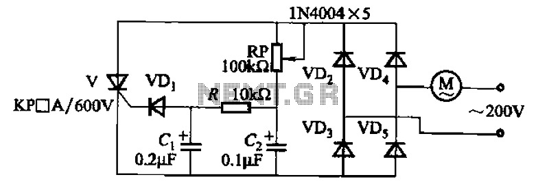
The circuit illustrated in Figure 3-11 employs a unidirectional thyristor control mechanism. An adjustable potentiometer, designated as RP, is utilized to continuously modify the motor speed. The circuit utilizes a unidirectional thyristor, also known as a silicon-controlled rectifier (SCR), which...