
PJRC MP3 Player Pushbutton Circuit Board
The described circuit primarily involves the integration of a PJRC display kit with a microcontroller or PC interface. The circuit's core components include the PJRC display, which requires a compatible firmware chip to operate effectively. The necessity for an EPROM programmer highlights the importance of proper firmware installation, ensuring that the display can interpret data correctly.
The MAX232 chip serves a dual purpose in this circuit: it converts RS-232 level signals from the PC to TTL levels suitable for the display while also providing negative voltage (-Vee) to maintain operational stability. The configuration of the power supply is simplified, requiring only a +5 volt source, which streamlines the setup process.
The pushbutton interface, although optional, enhances user interaction by allowing manual input commands to the display. The schematic for this interface is crucial for users who wish to implement additional control functionalities. The inclusion of hyperterminal at a baud rate of 19200 provides a straightforward method for sending data to the display, with the ability to execute control commands for advanced display management.
In conclusion, this circuit design emphasizes the importance of firmware compatibility, effective signal conversion, and user interface options, making it a robust solution for integrating a display with a microcontroller or PC system. Proper implementation of these components ensures reliable operation and expands the potential applications for the display system.This would be a lot easier with a display kit purchased from PJRC, which comes with the correct firmware installed on the display, a working pushbutton board, and the two cables needed. The PJRC display comes with a 4-pin plug that mates with the MP3 player, but it is easy to use with a PC instead of the MP3 player, as described above.
But with a raw display, the firmware chip that comes installed is useless and you must replace it with one that has the LCD. HEX firmware (that PJRC provides as a free download including source code, even though you purchased the LCD elsewhere!) You will need to program a flash rom or EPROM with LCD.
HEX and replace the socketed chip that came with the board. You will need an EPROM programmer, and the correct DIP-PLCC socket adaptor to hold the chip while it is in the programmer (beware, the common 32-to-28 pin adaptor will not work, you need 32-to-32). The socket is wired for a 32 pin flash rom pinout, not the 28-pin 27Cxxx eproms that have 4 unconnected pins when purchased in 32 pin PLCC.
I use the 39SF512 chip in the displays from PJRC. Update: now you can buy a pre-programmed firmware chip. PJRC provides these chips to allow you to make use of your JW-002 LCD (purchased from a third party), but PJRC does not provide the pushbutton board and custom ribbon cable separately for use with LCD purchased elsewhere. This step is absolutely required. If you don`t have an EPROM programmer, you must borrow or buy one, or find someone who has one to program the chips for you.
No matter how badly you want those displays to work, you`re not going to get far with the original chip that comes installed with AT&T`s old firmware. The display does not care if you have access to an EPROM programmer or not. If you can`t get a chip with LCD. HEX installed, you might as well just give up and throw the display in the trash. Once you`ve got workable firmware on the display, then all you really need to do is apply power and use a chip like the MAX232 to convert the RS-232 signals from your PC to the TTL levels needed on the display.
The MAX232 can also be used to provide -Vee, so you only need a single +5 volt power supply. The pushbuttons are optional. I put a complete schematic and layout for the pushbutton board on the web, so you can use it: To make something display from the PC, you could just run hyperterminal and set it to 19200 baud. Anything you type will (should, if you`ve done everything correctly) immediately appear on the display.
You can type the control command (they all begin with a backslash `` ) to do special things like position the cursor, change fonts, etc. You don`t need to learn any ASM. but you absolutely MUST replace the firmware chip that came with the display with one that has LCD. HEX (which is written in assembly source, but you can download a compiled LCD. HEX from Dave`s nightly build site and not worry about using the assembler at all). If you DO want to learn asm, you could write your own LCD. HEX, using my source code as a guide. There are instructions in the source for a set of mods to the board so it can run PAULMON2, which allows you to download your experimental code into half of the RAM on that board.
This is the approach I used to develop LCD. HEX, and Tom used a similarly mod`d board to develop his extensions (marquee horz scroll, double buffered write/update, etc) that are in today`s code. Those mods and this sort of code development are not for beginners! 🔗 External reference
Related Circuits
The circuit is designed to establish a monitoring and surveillance system for a remote location, functioning as a room monitor or baby alarm. The proposed circuit for the monitoring and surveillance system incorporates various electronic components to ensure reliable operation...

This circuit diagram of a digital clock utilizes six common anode seven-segment displays to indicate the time. It does not require microcontrollers or PICs for operation. The circuit operates using the MM5314 integrated circuit, functioning at either 50 Hz...
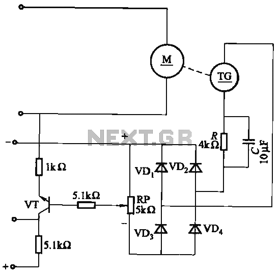
The capacitor C is part of the speed differential negative feedback system. The adjustment potentiometer RP allows for changing the amount of negative feedback. Both components can be utilized simultaneously within the circuit. The voltage (or speed) will only...
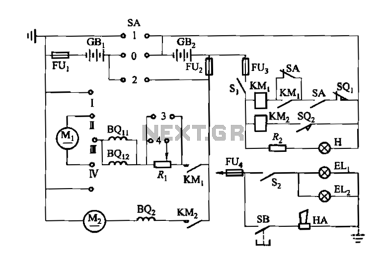
Denote cam controller SA 1 contact closure case. M1 is 1.35 kW driving motor, M2 is a 4 kW pump motor. The circuit involves a cam controller designated as SA 1, which is responsible for managing the operation of...
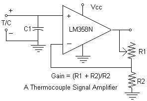
Continuing with the thermocouple interface concept, the next step is to amplify the TC's millivolt signal into a more readable analog voltage, on the order of 0 to 5VDC. This simple circuit fits the bill. The LM358N is a...
One of the more challenging aspects of creating a control or security system that utilizes a PC, such as a burglar alarm, is connecting the sensors to the computer. This typically requires specialized interface expansion boards, and programming that...
Warning: include(partials/cookie-banner.php): Failed to open stream: Permission denied in /var/www/html/nextgr/view-circuit.php on line 713
Warning: include(): Failed opening 'partials/cookie-banner.php' for inclusion (include_path='.:/usr/share/php') in /var/www/html/nextgr/view-circuit.php on line 713