
Classic Schematics
The provided schematics encompass a variety of electronic designs that may include circuit diagrams, component layouts, and functional descriptions of various electronic systems. These documents serve as valuable resources for engineers, hobbyists, and students seeking to understand or replicate specific circuit designs.
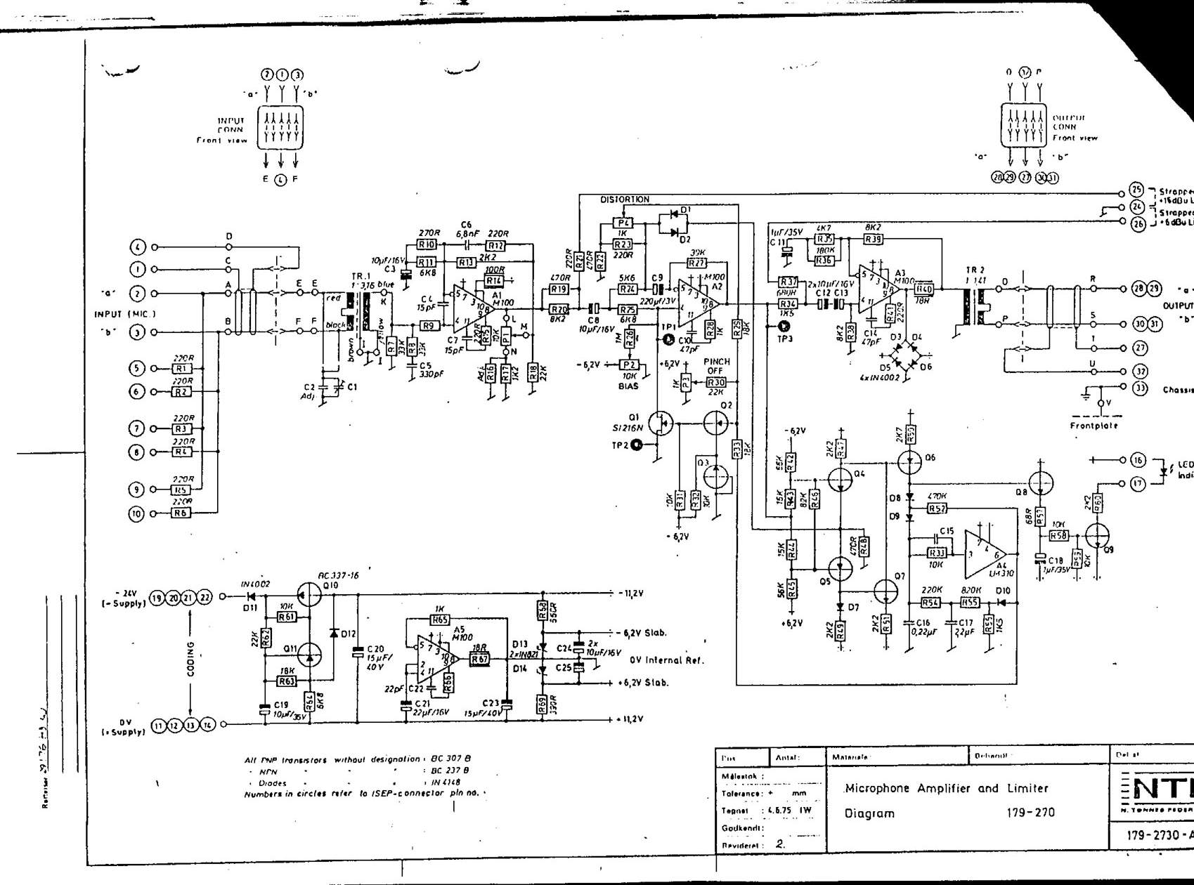
The schematics may cover a range of applications, such as audio amplifiers, power supplies, microcontroller interfaces, and more. Each schematic typically includes symbols representing electronic components such as resistors, capacitors, diodes, transistors, and integrated circuits. Additionally, the interconnections between these components are illustrated through lines that indicate electrical connections.
To ensure effective utilization of these schematics, it is important to understand the notation and symbols used within each document. For example, standard electronic symbols follow conventions established by organizations such as the Institute of Electrical and Electronics Engineers (IEEE). Familiarity with these symbols allows for easier interpretation and implementation of the designs.
Moreover, the inclusion of component values, power ratings, and operational parameters is essential for successful circuit construction. These details provide critical information for selecting appropriate components and ensuring that the circuit operates within its intended specifications.
In cases where larger GIF files do not render properly in web browsers, a recommended approach is to download the files directly to a local device. This method not only preserves the integrity of the schematic but also allows for offline viewing and analysis, which can be particularly beneficial for detailed examination and troubleshooting.
Overall, the collection of schematics aims to serve as a comprehensive reference for individuals engaged in electronic design and experimentation, fostering knowledge sharing and innovation within the electronics community.Here`s some schematics and information that can be hard to find elsewhere. If you have some schematics that you think belongs among these, please do not hesitate to contact me. I hope to be able to extend this little collection with time, so check back for updates. NOTE: Some of the larger. gif-files dosen`t show correctly in some browsers. If you have that problem, instead "right-click" on the link and select "save target as. " to save to your harddisk - and view it from there. 🔗 External reference
Related Circuits
This simple robot responds to light and avoids obstacles without the need for a microcontroller, programmer, or PC. The primary component in the circuit is a window discriminator, which functions as an advanced window comparator. Resistors R1 and R2,...
PIC C Compilers are utilized to compile source code, leveraging the extensive built-in functions offered by these compilers. A single C statement can produce multiple pages of PIC RISC instructions, eliminating the need for manual coding. CCS charges $125...
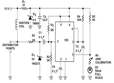
The sections available in this datasheet cover general design considerations for the 555 timer, frequently asked application questions (FAQ), design formulas, and examples of innovative applications. Examples of applications include a Missing Pulse Detector, Pulse Width Modulation (PWM), Tone...
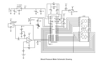
This digital circuit outlines a concept for a digital blood pressure meter that incorporates an integrated pressure sensor, analog signal conditioning circuitry, microcontroller hardware/software, and a liquid crystal display. The sensing system measures cuff pressure (CP) and extracts pulses...
An idea proposed is to utilize a phase shift oscillator followed by an inverter to convert a sine wave into a square wave; however, this may be considered a rudimentary solution. There is also interest in schematics for a...
Using a magnetic compass, ensure that both pickups have a South polarity on the top of each pickup. Verify this by checking for a North polarity on the bottom of the pickups. It is uncommon to find both pickups...