
discrete robot schematics
The robot's design incorporates fundamental principles of robotics and circuit design, making it an excellent project for those interested in electronics. The use of a window discriminator allows for adaptable light sensing, enabling the robot to navigate its environment effectively. The configuration of light-dependent resistors on either side of the robot is critical for its ability to respond to light gradients, facilitating autonomous movement toward brighter areas while avoiding obstacles.
The integration of the IR sensor enhances the robot's capability to detect nearby objects, ensuring that it can navigate safely. The choice of using pulsed light for obstacle detection is significant, as it reduces interference from ambient light and increases the reliability of the sensor's output. The robot's movement strategy, governed by the outputs of the window discriminator, allows for a straightforward yet effective method of navigating complex environments.
Additional features, such as the ability to follow a line or respond to varying light conditions, can be explored further by adjusting resistor values or experimenting with different sensor placements. The introduction of alternative sensors, such as ultrasonic detectors, broadens the robot's application potential, allowing for more sophisticated obstacle avoidance mechanisms.
In summary, this robot exemplifies a practical approach to building autonomous systems using basic electronic components. The design encourages experimentation and customization, making it suitable for educational purposes or hobbyist projects. The flexibility in the choice of components and configurations allows users to tailor the robot's behavior to their specific needs and preferences, fostering creativity and innovation in the field of robotics.This simple robot, which responds to light and avoids obstacles, can be built without using a microcontroller, programmer or PC. The only special` component in the circuit is a window discriminator (a fancy version of a window comparator).
Resistors R1 and R2 in combination with light-dependent resistors LDR1 and LDR2 form a voltage divider (with the current being limited by R1 and R2 for bright light). Window discriminator TCA965 compares the mid-point voltage with an upper threshold value (adjustable using P1) and a lower threshold value (adjustable using P2). Outputs AU, AI, AO, and AA go High if the voltage lies below, inside, above or outside this window, respectively; otherwise they remain Low.
Output AA switches transistor T1, which drives the right-hand motor. The light-dependent resistors can be attached on the left and right sides of the vehicle, or at the front and rear. This causes the robot to turn to the right, due to the motor on one side being stopped, until the desired lighting relationship is restored.
The vehicle will then continue to travel in a straight line until the lighting relationship again changes, at which point it will again turn, and so on. You can experiment with various behaviour patterns by using the other outputs of the window discriminator.
If a transistor is provided for each of the AU and AO outputs of the TCA965, the robot can be made to travel toward or away from a light source, depending on the connections. Using the window discriminator, the robot will operate under the rules of a three-point controller (left, straight ahead, or right).
If you fit the light-dependent resistors in a box under the vehicle together with a light source, you can try to have the robot follow a black line on a white background. A reflective IR sensor enables the robot to respond to obstacles. This not as simple as it might seem, since the Sharp IS471 operates the IR LED with pulsed light and uses sophisticated detection processing.
When an obstacle is detected, the output (pin 2) goes Low and blocks transistor T2. This causes the motor to stop, and the vehicle will rotate about the stationary wheel until the obstacle is no longer in its path. The sensitivity of the IS471 can be set using P3. As its range is only around 10 15 cm, the vehicle must not travel too quickly, since otherwise it will not be able to avoid obstacles in time.
This part of the circuit is also open for experimentation. If a relatively large and fast robot requires an obstacle detector (or isn`t fitted with the IS471), an ultrasonic detector can also be used. Suitable complete construction kits are available from Conrad, for example. You can also fit a suitable mechanical push-button switch mounted on a flexible rod. The obstacle detector can also drive a warning buzzer or a lamp; the circuit leaves lots of room for your own ideas.
The circuit works over a wide range of supply voltages from 4. 5 to 16 V. If larger motors are used, transistors with increased power-handling capacity and heavier batteries are necessary. The author connected two 4. 8-V rechargeable batteries in series and used BC388 transistors as drivers for Lego micro-motors. You can build the robot entirely according to what you have in your parts box. The mechanical elements can also be freely selected, but they partially determine the behavior and operation of the robot.
The author`s robot is made from a Lego chassis with a prototyping board holding the circuitry attached using elastic bands. The motors are fitted on the left-hand and right-hand sides. The third wheel at the front can turn freely. One problem must be mentioned: if an obstacle is detected while an incorrect lighting relationship is present, the vehicle remains standing.
In this case, a bit of logic could be added to cause both motors to rotate in reverse. However, that would require directional switches for the motors or motor driver ICs (L293D). The simple circuit would become more complicated and larger, and at some point you would end up using a microcontroller after all - but that`s just the point of the story. 🔗 External reference
Related Circuits
The motion games on the Nokia 5800 sparked an interest in creating a real-world version of a racing car controlled by tilting a phone. The motion-controlled robot, named Hercules due to its high torque and speed, is operated via...
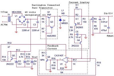
The switching power supply provides 12 volts at a maximum of 10 amps, utilizing a discrete transistor regulator with an operational amplifier acting as a comparator in the feedback circuit. The schematic does not depict the front panel power-on...
Most components have been assembled for the electrical aspect of the project. Serial communication is nearly operational and will utilize a Teensy 2.0 chip to communicate via serial USB with the Mega128. A TTL UART serial driver, such as...
PIC C Compilers are utilized to compile source code, leveraging the extensive built-in functions offered by these compilers. A single C statement can produce multiple pages of PIC RISC instructions, eliminating the need for manual coding. CCS charges $125...
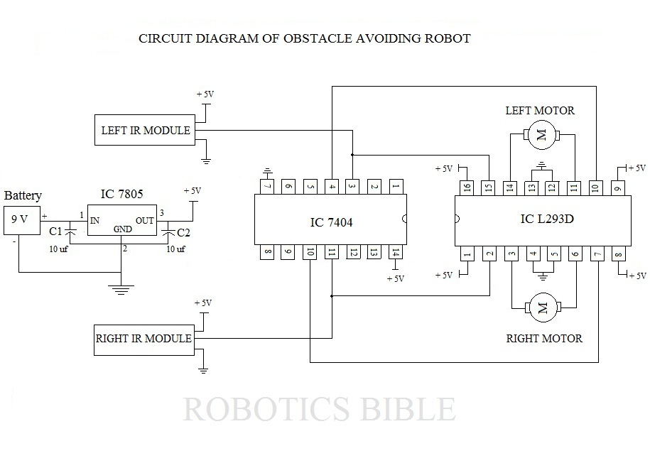
An obstacle-avoiding robot is an intelligent device that can automatically sense and navigate around obstacles in its path. It is designed without a microcontroller to simplify the circuitry and programming requirements. Understanding the circuit diagram is essential for constructing...

The circuit diagram illustrates a sound, light, and touch-controlled delay self-extinguishing switch. It comprises three main sections: the power circuit, the signal conversion detecting circuit, a delay circuit, and a control circuit. 1. Power Circuit: This section consists of...