
clock

The digital clock project designed for educational purposes incorporates a straightforward yet effective circuit architecture. The clock's primary component is the microcontroller, which in the original design is the 16F84 PIC, programmed in assembly language. This choice allows for precise control over the LED outputs, essential for displaying the time accurately. The redesign to accommodate a circular PCB simplifies manufacturing while maintaining functionality. The use of a Picaxe 18X IC in later iterations reflects the evolving preferences in educational programming environments, making the system more accessible for students and educators.
The multiplexing technique employed in the circuit is critical for managing the twelve outputs required for a standard clock face. By utilizing two transistors, the design efficiently switches between two banks of LEDs, resulting in a reduction of the number of outputs needed from the microcontroller. This approach conserves resources while ensuring that all necessary functions are performed, showcasing an effective application of digital electronics principles.
The physical design of the clock, featuring an aluminum tube casing with acrylic end caps, not only provides durability but also aesthetic appeal, making it suitable for classroom environments. The inclusion of a plinth for stability enhances usability, allowing the clock to be placed on various surfaces without risk of tipping over.
The additional requirement of a resistor between pins 3 and 5 serves as an important detail for circuit integrity, ensuring that the clock operates reliably. The distinction between the Picaxe 18X and 16F627 microcontrollers highlights the flexibility of the design, allowing educators to choose components based on availability or preference while still achieving the same functionality.
Overall, this digital clock project exemplifies an effective blend of educational utility, practical design, and robust electronic engineering principles, making it a valuable tool for teaching electronics in schools.A series of digital clocks, all with LED outputs, were created for the Electronics in Schools Strategy (EiSS) and used in several of the courses run on behalf of SETPOINT (now STEMPOINT) Devon & Cornwall for secondary school teachers in the south west. The original clock had two rows of LEDs that are just about visible on the centre of the image ( left). It used 16F84 PICs and the code for these was written in assembly language, the ICs being programmed with my parallel port programmer which can be seen in the Programmers section. Due to the expense and complexity of producing the acrylic cases for the original clock a more simple design was created based on a circular pcb board.
Again the PIC was programmed in assembly as this gave the option of allocating outputs to twelve of the ports and still leaving an input available for setting the time. The case consisted of a section of aluminium tube with an acrylic front and rear face machined to locate securely on the tube.
The acrylic faces also had a small plinth which allowed the clock to stand upright on a smooth surface. As schools gradually adopted the Picaxe PIC programming system, the pcb design above was modified to accommodate a Picaxe 18X ic.
In order to acquire the twelve outputs that are necessary for a clock face, six outputs from the PIC were multiplexed via two transistors to switch either bank of LEDs on, hence providing twelve outputs. The whole circuit was assembled in an identical case to that shown above. The PIC was programmed externally to the project in one of Revolution Education`s programmers. The two drawings above indicate the location of the components on the pcb. In order for the clock to work correctly an additional resistor has to be added between pins 3 & 5 - (see right image) This is the circuit diagram for the multiplexed clock.
A Picaxe 18X ic is required due to memory limitations on the other Picaxe 18 chips. A 16F627 can also be programmed in assembly to achieve the same functions. The PCB mask for the circuit can be downloaded here. 🔗 External reference
Related Circuits
This is the second part of the square root algorithm. It was developed during the final stages of finishing this website and reviewing this document for publication. While Part I focused on an empirical discovery for a sequential algorithm...
This oscilloscope clock project utilizes a PIC 16F876 microcontroller and a digital-to-analog converter (DAC) to generate X and Y signals for displaying a clock on an oscilloscope. The original circuit and software were designed by OZ2CPU. The clock circuit...
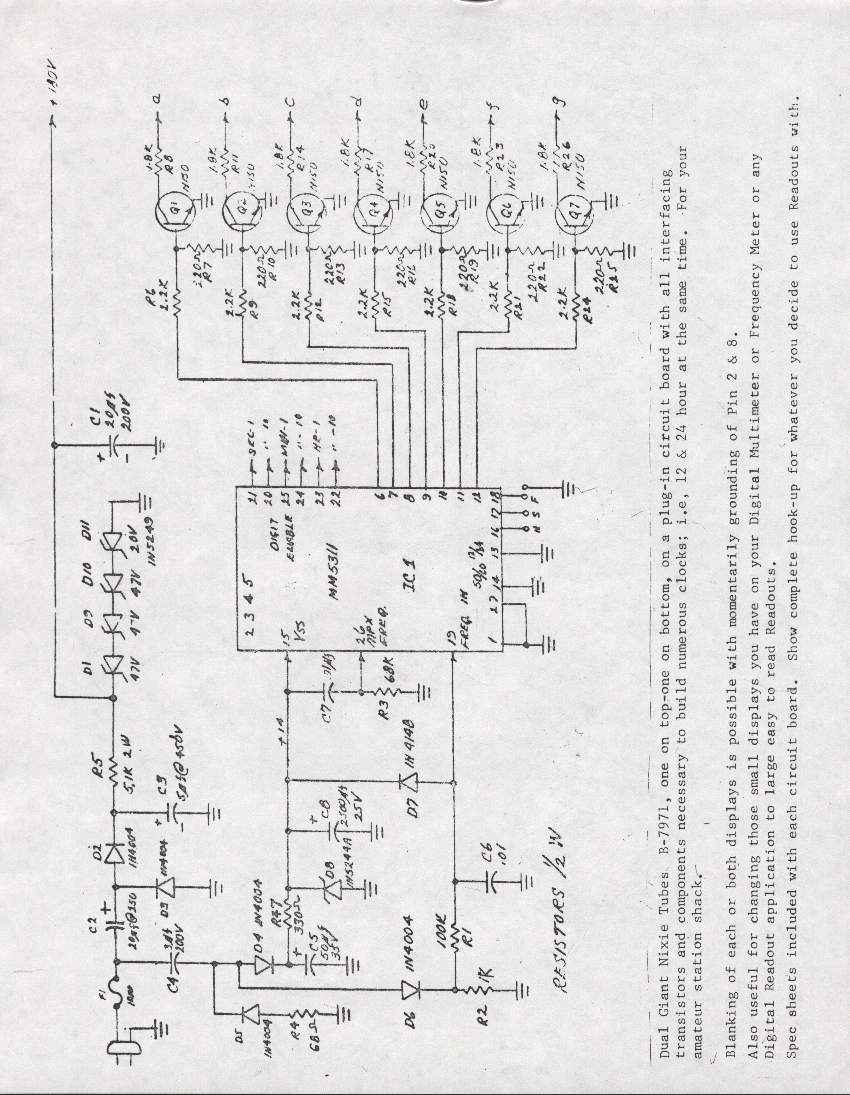
A Burroughs B-7971 Nixie Tube clock was constructed in 1979 during the senior year of high school. The digits measure 2.5 inches in height, enabling visibility from anywhere in the bedroom without the need for glasses. The clock circuit...
This is a programmable clock timer circuit that utilizes individual LEDs to display hours and minutes. Twelve LEDs can be arranged in a circular pattern to represent the 12 hours on a clock face, while an additional 12 LEDs...
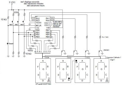
A digital clock project utilizing the PIC16C54 microcontroller can be constructed using the provided circuit diagram. This electronic project features a straightforward time-of-day clock that includes four seven-segment LED displays and three input switches, along with an additional reset...
The WWVB signal is broadcast as a 60 kHz carrier that is AM modulated with a time code frame that is updated once per minute. The data rate is one bit per second. Along with time code information, the...