
Crystal Oscillator Frequency Converter
The circuit functions as a frequency divider, utilizing a crystal oscillator to generate a stable 10 MHz signal. The 7404 hex inverter is employed to achieve the necessary signal manipulation for frequency conversion. Each inverter stage within the 7404 can be configured to create a series of toggling states that effectively halve the frequency of the input signal.
The crystal oscillator is the primary frequency source, ensuring precision and stability in the output frequency. The output from the oscillator is fed into the first inverter stage of the 7404, where the signal is inverted. This inversion process introduces a phase shift, which is critical for the subsequent stages of frequency division.
By cascading multiple inverter stages, the circuit can achieve the desired output frequency of 1 MHz. Specifically, two stages of inversion will divide the original 10 MHz signal down to 2.5 MHz, and further signal processing or additional inverter stages can be utilized to achieve the final 1 MHz output. The design may also include passive components such as resistors and capacitors to filter the output signal and stabilize the operation of the inverter stages.
This configuration is useful in various applications where a lower frequency signal is required from a higher frequency source, such as in signal processing, communication systems, and clock generation for digital circuits. Careful attention must be given to the power supply and grounding to minimize noise and ensure reliable operation of the frequency converter.The circuit was designed to create a frequency convert with the use of a crystal oscillator for the conversion of 10 MHz to 1 MHz. 7404 a hex inverter u.. 🔗 External reference
Related Circuits
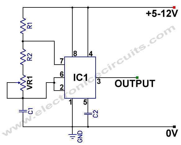
555 Variable Frequency Square Wave Generator. This simple 555 Variable Frequency Square Wave Generator produces a variable frequency output. The 555 Variable Frequency Square Wave Generator is a versatile circuit that utilizes the 555 timer IC to generate square wave...
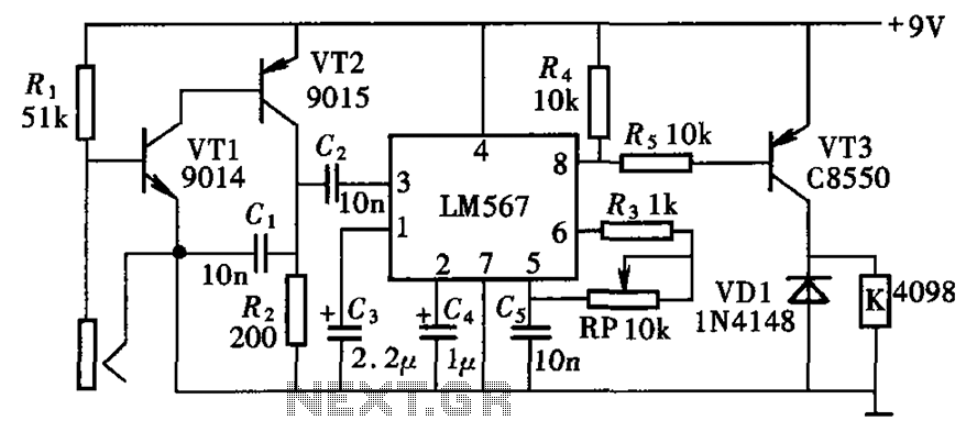
The electronic lock circuit is based on the frequency characteristics of the LM567 audio decoder. This circuit utilizes the audio decoding feature of the LM567, which outputs a low signal when the input signal frequency matches the oscillation frequency...

The TPS6420x controller is designed to operate from one to three series-connected cells or from a 3.3 V or 5 V supply obtained from a USB port. At its output, it can produce 3.3 V at 2 A, suitable...
This frequency doubler using a single 4069 hex inverter IC, a frequency doubler can be constructed to give an output pulse train whose frequency is twice that of a squarewave input signal. The signal is applied to the input...
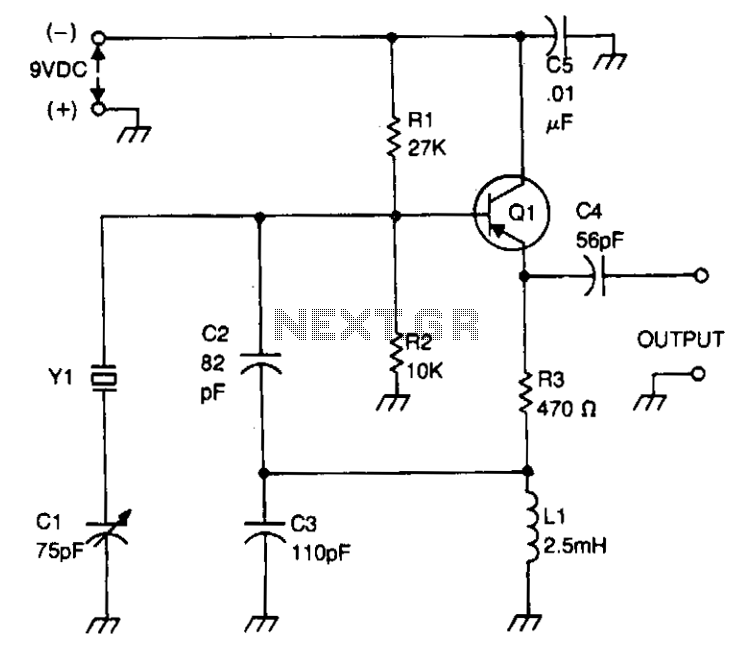
Bias for the PNP bipolar transistor is supplied by a resistor voltage divider network consisting of resistors R1 and R2. The collector of the oscillator transistor is maintained at AC ground through a capacitor C5, which is positioned near...
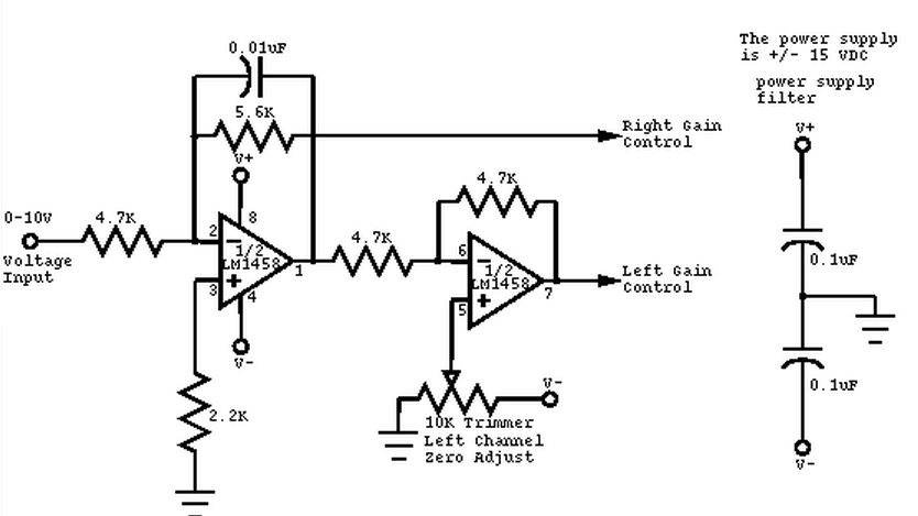
This circuit converts a mono audio signal into a stereo signal that can be panned between the left and right channels using a 0-10V control signal. It is designed for analog synthesizer systems. The circuit operates by taking a single...
Warning: include(partials/cookie-banner.php): Failed to open stream: Permission denied in /var/www/html/nextgr/view-circuit.php on line 713
Warning: include(): Failed opening 'partials/cookie-banner.php' for inclusion (include_path='.:/usr/share/php') in /var/www/html/nextgr/view-circuit.php on line 713