
Clock using analogue multimeters ( PIC16F628A )
Since the meter displaying the seconds is being updated every second there was a tendency for it to bounce from one value to the next. Just like there are watches with ticking second hands and smooth second hands I also wanted this clock design to emulate either mode. If the Smooth second jumper is in the 10th of a second values are introduced into the calculation of the PWM value of the second hand which results in a very smooth moving second hand.
The meter was designed to be plugged in to AC power using a wall adapter but I wanted a way for the time to be maintained in the event of a power outage. The system needs to know when the clock is running on backup power so that it can reduce the amount of power that is being used. This is done with the controllers Main Power Monitor pin. If this pin is grounded the system knows that it’s on battery backup and will drop power to the 3 meters and the heart beat LED.
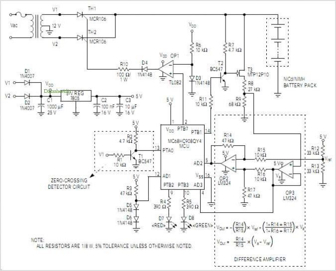
To implement the battery backup and main power loss monitoring 4 diodes and a resistor were used. D2 is used to raise the regulated power output to around 5.7 volts, D4 is used to feed a 5 volt signal to the Main Power Monitor line when the system is operating from main power. If the main power is lost R5 pulls the Main Power Monitor to ground. Component D3 is used to feed the main 5 volt power that the circuit runs from. The 4.5 volt battery backup power is connected to the 5 volt circuit via D5. The 4.5 volts is fed from 3 AA batteries. The battery pack didn’t come in before the project was complete but it will be the typical plastic battery holder that accepts 3 AA batteries and has two leads coming out. These leads will simply be tied into terminal block TB2.
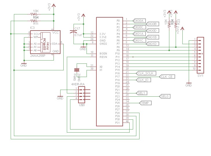
The Multimeter Clock design incorporates a robust timekeeping mechanism utilizing a 16F628A PIC microcontroller, which manages the time display across three distinct multimeters—one for hours, one for minutes, and one for seconds. The microcontroller is programmed to handle the user input through three dedicated buttons for adjusting the time. Each button is connected to a GPIO pin on the PIC, allowing for easy manipulation of hours, minutes, and seconds. The microcontroller also employs an interrupt-driven approach, firing an interrupt every 100ms to maintain accurate timekeeping by incrementing a tenths-of-a-second counter.
The multimeters operate in a 0.5 DCmA mode, with their negative leads grounded and positive leads connected to the microcontroller outputs through current limiting resistors. The choice of a 4.7K resistor is based on typical meter requirements, but it is crucial to ensure that the PIC microcontroller's output does not exceed 25mA for any of the meters. The design also includes a PWM mechanism to control the current supplied to the meters, allowing for precise needle positioning. The initial PWM value is set to 50% to prevent damage during startup, and a scale adjustment mode allows the user to calibrate the PWM for each meter, storing the values in non-volatile memory.
To enhance the user experience, the second-hand movement can be configured for either a smooth or ticking motion based on the state of a jumper. This feature is implemented by adjusting the PWM value used for the second-hand meter, resulting in a visually appealing clock behavior.
For power management, the system is designed to operate from an AC wall adapter while also providing battery backup via three AA batteries. The integration of diodes and a resistor enables the microcontroller to monitor the power status and switch to battery operation seamlessly when necessary. The Main Power Monitor pin is crucial for this function, as it detects when the system is running on backup power, allowing for power conservation by disabling the multimeters and heartbeat LED. The overall architecture of the circuit ensures that the clock remains functional and accurate even in the event of a power outage.The Multimeter Clock consists of three multimeters, the first meter displays hours, the second displays minutes and the last displays seconds. A 16F628A PIC microcontroller keeps track of time and outputs a calculated current to each meter to display the current time.
The user enters the time by pressing three time adjust buttons. The first button increments the hours, the second button increments the minutes and the third button resets the seconds. Once the time has been entered the microcontroller will keep track of time from there. An interrupt fires every 10th of a second to increment a 10th second counter. Another routine checks to see if we have at least one full second of time, if we do the current time is incremented by a second.
The microcontroller has a separate output for each of the three meters. The meters are all in 0.5 DCmA mode, the negative lead of each meter is grounded and the positive leads are connected to a microcontroller output via a current limiting resistor. The resistor in this case is a 4.7K however this can be adjusted depending on the meter current scale available.
Keep in mind that the PIC can deliver a maximum of 25mA to each meter so a meter with a lowest setting above 25mA would not work without additional circuitry. You also want to make sure that you can easily drive the meter to full scale, if the meter is not very accurate it could take 10 or 20% more than the stated current to drive it to full scale.
See the table 1 below for a few suggested resistor values. The controller uses PWM (pulse width modulation) to pulse the current to the 3 meters which allows for precise needle position. For example if the minute meter needs to display 30 then the PWM would be half of the pulses needed to show full scale.
When the system is initially started the PWM value is 50% so that the meters aren’t damaged by being accidentally overdriven. Originally the current limiting resistors were going to be a resistor and a calibration pot so that the full scale current to be adjusted by turning a pot.
To get rid of the requirement of 3 calibration pots a scale adjustment mode was created. This allows the user to set the PWM value needed to bring each of the 3 meters to full scale. This value is then stored to non-volatile memory so that it never needs to be touched again. Since the meter displaying the seconds is being updated every second there was a tendency for it to bounce from one value to the next. Just like there are watches with ticking second hands and smooth second hands I also wanted this clock design to emulate either mode.
If the Smooth second jumper is in the 10th of a second values are introduced into the calculation of the PWM value of the second hand which results in a very smooth moving second hand. The meter was designed to be plugged in to AC power using a wall adapter but I wanted a way for the time to be maintained in the event of a power outage.
The system needs to know when the clock is running on backup power so that it can reduce the amount of power that is being used. This is done with the controllers Main Power Monitor pin. If this pin is grounded the system knows that it’s on battery backup and will drop power to the 3 meters and the hear beat LED.
To implement the battery backup and main power loss monitoring 4 diodes and a resistor were used. D2 is used to raise the regulated power output to around 5.7 volts, D4 is used to feed a 5 volt signal to the Main Power Monitor line when the system is operating from main power. If the main power is lost R5 pulls the Main Power Monitor to ground. Component D3 is used to feed the main 5 volt power that the circuit runs from. The 4.5 volt battery backup power is connected to the 5 volt circuit via D5. The 4.5 volts is fed from 3 AA batteries. The battery pack didn’t come in before the project was complete but it will be the typical plastic battery holder that accepts 3 AA batteries and has two leads coming out.
These leads will simply be tied into terminal block TB2. 🔗 External reference
Related Circuits
After constructing numerous Nixie Tube Clocks based on online designs, a personal design was developed. This clock utilizes IN-12 Nixie Tubes and an 8-core Propeller Microcontroller. Although the Propeller may be more powerful than necessary for this task, it...
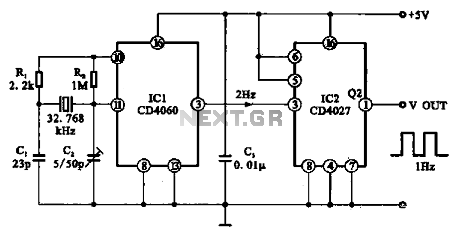
A 1Hz clock signal generator circuit is presented, which demonstrates a sophisticated clock signal generating mechanism. This circuit can be utilized for digital clocks and timing applications. It comprises a binary counter (CD4060), a JK flip-flop (CD4027), and a...
The TDA 2030, produced by SGS Ates, is a complete audio amplifier. It is a Class AB amplifier capable of delivering 14 watts into a 4-ohm load with a power supply of ±14V. By connecting two TDA2030 amplifiers through...
The motion games on the Nokia 5800 sparked an interest in creating a real-world version of a racing car controlled by tilting a phone. The motion-controlled robot, named Hercules due to its high torque and speed, is operated via...
The SN74AVCA406E is a transceiver designed for interfacing microprocessors with MultiMediaCards (MMCs), secure digital (SD) cards, and Memory Stick compliant products. It is manufactured by Texas Instruments. The SN74AVCA406E transceiver is a versatile device that facilitates communication between microprocessors and...
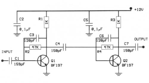
The following circuit illustrates a 20 dB VHF amplifier circuit diagram utilizing the BF197 transistor. Features include a simple circuit design. The 20 dB VHF amplifier circuit is designed to amplify very high frequency signals, making it suitable for applications...
Warning: include(partials/cookie-banner.php): Failed to open stream: Permission denied in /var/www/html/nextgr/view-circuit.php on line 713
Warning: include(): Failed opening 'partials/cookie-banner.php' for inclusion (include_path='.:/usr/share/php') in /var/www/html/nextgr/view-circuit.php on line 713