
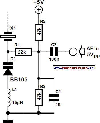
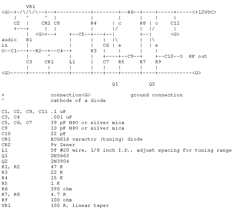
CMOS Crystal Frequency Multiplier
Frequency multipliers are essential components in electronic circuits, especially when higher frequency signals are needed beyond the limitations of standard crystal oscillators. A frequency multiplier works by taking an input signal at a specific frequency and generating an output signal at a frequency that is a multiple of the input frequency.
In the context of crystal oscillators operating at fundamental frequencies up to 15 MHz, the frequency multiplier can significantly enhance the performance of the circuit. For instance, if a crystal oscillator operates at 10 MHz, a frequency doubler can be used to produce a 20 MHz output. This is achieved through non-linear processes, often involving diodes or transistors configured in specific ways to achieve the desired multiplication factor.
The design of a frequency multiplier involves careful consideration of the circuit topology, the components used, and the desired output frequency. Common configurations for frequency multiplication include the use of harmonic generation techniques, where the input signal is applied to a non-linear device that generates harmonics of the input frequency. Filters are then employed to isolate the desired harmonic and suppress unwanted frequencies.
Additionally, the choice of components such as inductors, capacitors, and the non-linear devices themselves can greatly influence the efficiency and performance of the frequency multiplier. Proper impedance matching is also crucial to ensure maximum power transfer and minimize signal loss.
In summary, frequency multipliers serve as vital tools in electronic design, enabling the generation of higher frequency signals from lower frequency crystal oscillators, thereby expanding their application in various fields such as telecommunications, signal processing, and RF communication systems.Crystals usually operate at fundamental frequencies up to about 15 MHz. Whenever higher frequencies are required a frequency multiplier is placed after th.. 🔗 External reference
Related Circuits
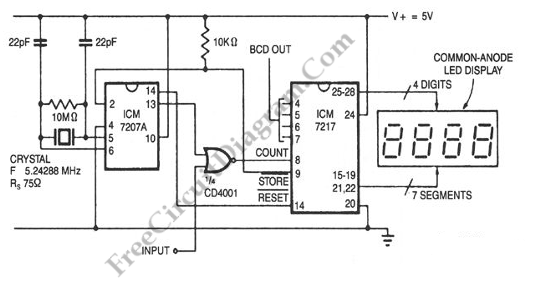
For convenient reading, the display of this tachometer circuit shows the reading in hertz directly. The conversion time will be equal to the gating time. The tachometer circuit is designed to provide a direct digital readout of rotational speed in...
A 1 Hz pulse frequency generator utilizes the widely used timer IC 555 configured as an Astable Multivibrator. The output pulses can be visually indicated by an LED. An Astable Multivibrator, often referred to as a free-running Multivibrator, is...
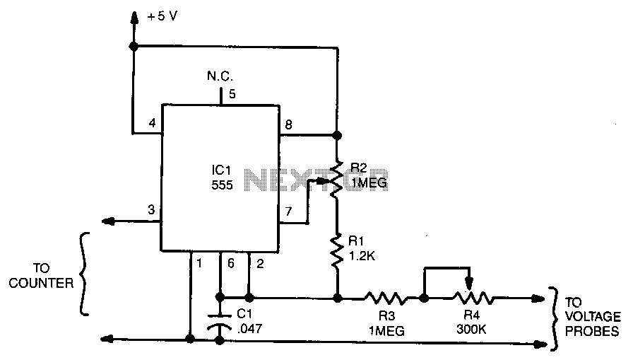
The output frequency from IC pin 3 is determined by the voltage input to pin 6. A standard frequency counter can be used to measure voltages directly over a limited range from 0 to 5 V. In this circuit,...
The world is full of xtal oscillators twiddled by digital designers lacking in the analog design knowledge necessary. Just look at all the PC real time clocks that lags or leads by several minutes per day. And they eat...
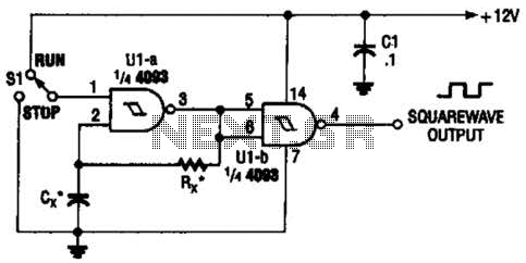
Two gates of the Quad 4093 are utilized to create an oscillator. The resistor (R) can range from approximately 5 kΩ to around 10 kΩ. The capacitor (Cx) can vary from about 10 pF to higher values, with the...
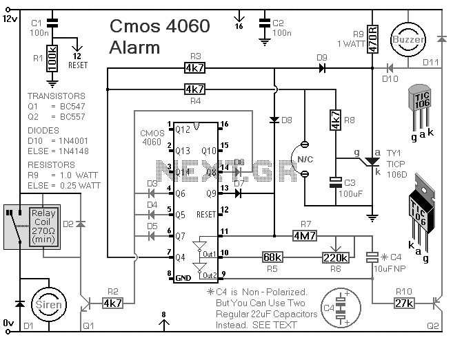
This is a single-zone alarm system equipped with automatic exit, entry, and siren cut-off timers. It can accommodate various types of normally-closed input devices, such as magnetic reed contacts, foil tape, and passive infrared sensors (PIRs). Additionally, it is...