
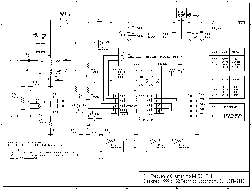
Frequency Counter Tachometer
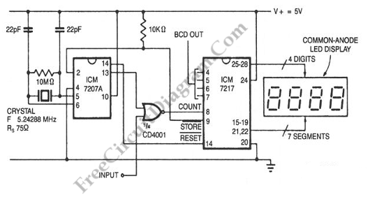
The tachometer circuit is designed to provide a direct digital readout of rotational speed in hertz, facilitating easy interpretation of the measurements. The circuit utilizes a frequency-to-voltage converter, which translates the input frequency derived from the rotating object into a proportional voltage. This voltage is then processed by an analog-to-digital converter (ADC) to display the frequency in hertz on a digital screen.
The gating time, which is the duration over which the input signal is measured, is critical in determining the accuracy of the readings. By synchronizing the conversion time with the gating time, the circuit ensures that the frequency measurement reflects the true operational speed of the motor or shaft being monitored.
To implement this circuit, essential components include a microcontroller to handle the ADC and display interface, a frequency sensor (such as a Hall effect sensor or an optical encoder) to detect the rotational speed, and a display module (such as a seven-segment display or an LCD) to present the output. The microcontroller is programmed to initiate the ADC at the end of each gating interval, ensuring that the displayed value corresponds to the frequency measured during that time frame.
The tachometer circuit can be powered by a standard DC power supply, and it is advisable to incorporate filtering capacitors to stabilize the power supply voltage. Additionally, proper signal conditioning may be required to filter out noise from the frequency sensor, ensuring that the readings are accurate and reliable.
Overall, this tachometer circuit design provides a straightforward yet effective solution for measuring rotational speed in real-time, making it suitable for various applications in industrial and automotive settings.For convenient reading, the display of this tachometer circuit show inthe reading in hertz directly.? The conversion time will be equal to the gating time,. 🔗 External reference
Related Circuits
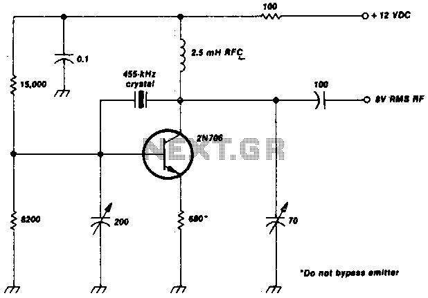
This crystal-oscillator circuit utilizes a 455-kHz crystal. It is a straightforward project. The crystal oscillator circuit based on a 455-kHz crystal operates by utilizing the piezoelectric properties of the crystal to generate a stable frequency. The circuit typically consists of...

A simple frequency meter or frequency counter circuit featuring an LCD display and an AVR microcontroller. This includes a DIY schematic circuit diagram and embedded C code. The frequency meter circuit is designed to measure the frequency of input signals...
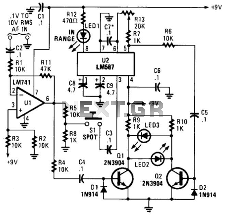
This meter is unique as it does not utilize a D'Arsonval movement or digital display for frequency readings. Instead, the measured frequency is indicated on a hand-calibrated dial. Any audio signal applied to the circuit is amplified by U1,...
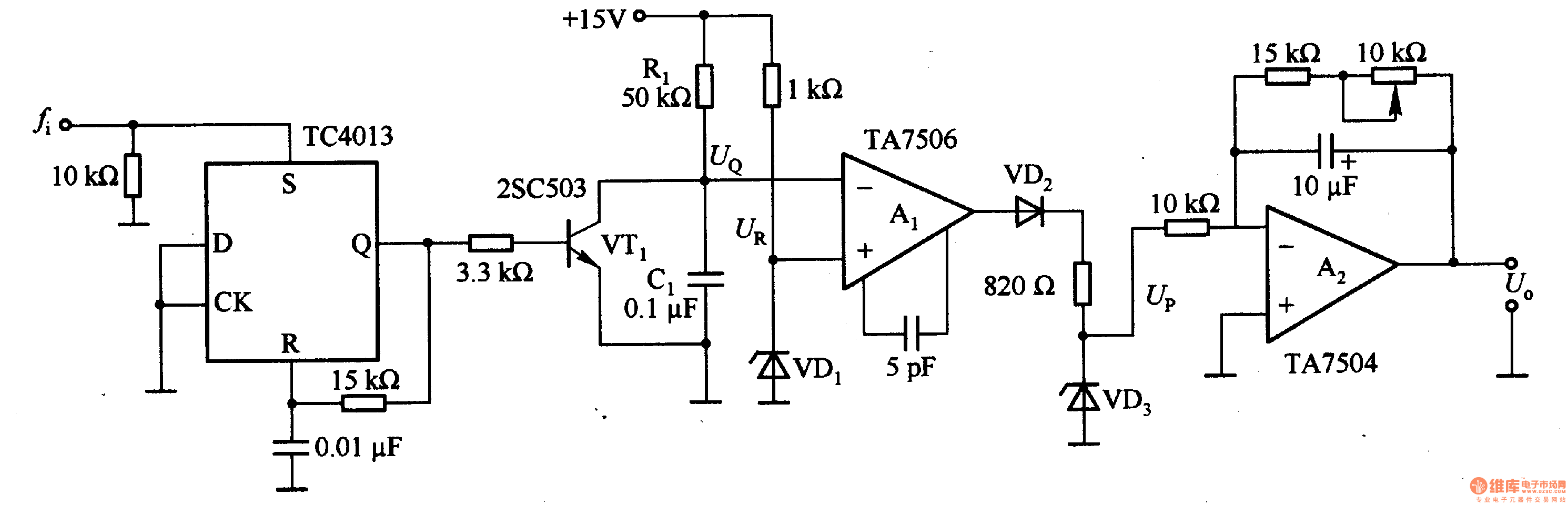
This circuit can convert an input frequency ranging from 0 to 100 Hz into an output voltage of 0 to 10 V. It utilizes the TC4013 monostable multivibrator to shape and amplify the input pulse, which has a width...
This is an image Schematic. No Description available. The provided input indicates that there is an image schematic without any accompanying descriptive details. In the absence of specific schematics or circuit details, it is essential to consider the typical...
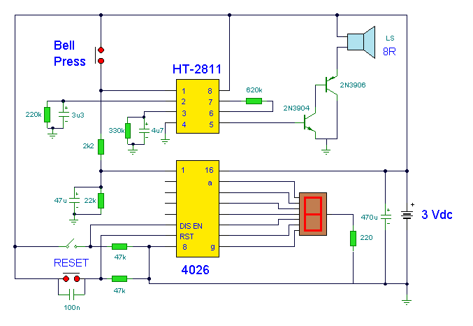
This circuit utilizes a synthesized sound chip from Holtek, the HT-2811, which produces the sound of a "ding-dong" chiming doorbell. Additionally, it incorporates a CMOS 4026 counter display driver integrated circuit (IC) to tally the number of visitors. The...