
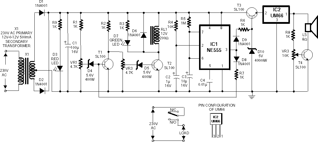
1 Hz Pulse Frequency Generator with 555

The described circuit operates as a continuous pulse generator, producing a square wave output at a frequency of 1 Hz. The configuration of the 555 timer in astable mode allows it to oscillate between high and low states without external intervention, making it ideal for applications such as clock generation, LED blinking, and timing applications.
In the circuit, the two resistors, R1 and R2, along with the capacitor C1, determine the frequency and duty cycle of the output waveform. The values of R1 and R2 can be adjusted to modify the timing characteristics of the pulse generator. The duty cycle can also be influenced by the relative values of R1 and R2, allowing for customization of the output signal depending on the requirements of the specific application.
The output from the timer IC can be connected to other components in a circuit, such as LEDs for visual indication or other digital circuits requiring clock pulses. The design is straightforward and can be easily implemented on a breadboard or a printed circuit board (PCB). The simplicity of the 555 timer and the astable configuration makes it a popular choice for hobbyists and engineers alike when creating timing circuits.
In summary, the 555 timer configured as an Astable Multivibrator serves as an effective solution for generating a stable 1 Hz pulse signal, with adjustable frequency and duty cycle characteristics, suitable for a wide range of electronic applications.A 1Hz pulse/frequency generator using the popular timer IC 555 which is wired as an Astable Multivibrator. The output pulses can be indicated visually by the LED. An Astable Multivibrator, often called a free-running Multivibrator, is a rectangular-wave generating circuit.
Unlike the Monostable Multivibrator, this circuit does not require any external trigger to change the state of the output, hence the name free-running. This circuit can be used in applications that require clock pulses. An Astable Multivibrator can be produced by adding resistors and a capacitor to the basic timer IC 555. The timing during which the output is either high or low is determined by the externally connected two resistors and a capacitor.
Clock: A clock is simply a square wave i. e. alternate high & low states. Each alternate high-low forms a clock cycle with a specific frequency & duty cycle. Frequency is the number of cycles completed in 1 sec & duty cycle is the ratio of the time period of high state to the time period of the low state. Capacitor C1 begins charging toward VCC through resistances R1 and R2 (VR). Because of this, the charging time constant is (R1 + R2( VR) C. Eventually, the threshold voltage exceeds +2/3 VCC, the comparator 1 has a high output and triggers the flip-flop so that its Q is high and the timer output is low.
With Q high, the discharge transistor saturates and pin 7 grounds so that the capacitor C1 discharges through resistance R2 (VR) with a discharging time constant R2 C. With the discharging of capacitor, trigger voltage at inverting input of comparator 2 decreases. When it drops below 1/3VCC, the output of comparator 2 goes high and this reset the flip-flop so that the timer output is high.
This proves the auto-transition in output from low to high and then to low. Thus the cycle repeats. 🔗 External reference
Related Circuits
This tiny circuit comprising of a single 3 terminal IC UM66 can be built small enough to be placed inside a greeting card and operated off a single 3V flat button cell. There is not much to the circuit....
The output signal is configured to go high for approximately 0.5 seconds and then low for around 1.33 seconds. However, there is an issue present. The circuit in question likely employs a timing mechanism to achieve the specified output signal...
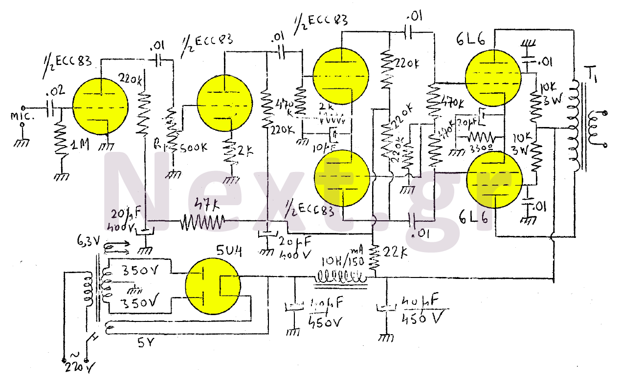
The amplifier in this design is rated at 30 Watts and is intended for use with a microphone. It is compatible with a crystal microphone and can be utilized for speeches, lectures, as a transmitter modulator, and in applications...
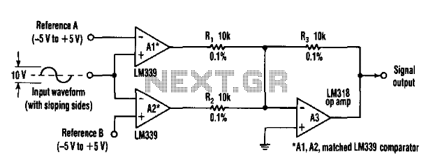
This circuit can extract harmonics from various waveforms. With a sloped input waveform, the comparator produces a pulse width that is proportional to a reference plus input amplitude. As the pulse width changes, the harmonics spectrum changes. Combining the...
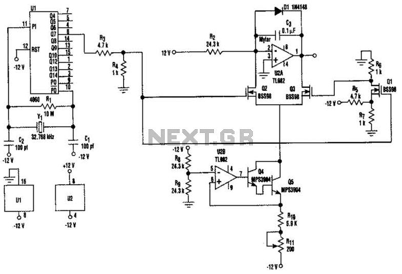
U2-a, U3, and R2 function as an integrator. Q2 and Q3 are alternately switched at 256 cycles. U2-b, Q4, Q5, and R8 through R11 form a constant current generator, with R11 configured to produce a symmetrical triangular waveform. The circuit...
The circuit is a standard RC phase shift oscillator that utilizes a single bipolar transistor as the active component. When power is supplied, regenerative feedback is applied through capacitor C2 from the collector to the base of the transistor....