
CMOS Toggle Flip Flop Using Laser Pointer
The circuit design incorporates an IR photo transistor as a critical component for detecting laser light. When the laser pointer is aimed at the photo transistor, it triggers a voltage increase sufficient to activate the relay, thus allowing for remote control applications. The use of a 4.7 µF capacitor is significant as it not only serves to delay the reset of the circuit but also ensures stable operation by preventing rapid toggling, which could lead to erratic behavior. The 10K resistor plays a dual role; it helps to limit current through the diode for safe operation while also facilitating faster capacitor discharge, enabling quick reactivation of the relay.
In applications where the circuit may be exposed to varying ambient light conditions, the shielding of the photo transistor becomes crucial to maintain reliable operation. Adjusting the 3K series resistor allows for fine-tuning of the sensitivity of the photo transistor, ensuring that it responds optimally to the laser light without being overly sensitive to other light sources. The choice of a solid-state relay is advantageous for applications involving resistive loads, as it offers faster switching times and increased durability compared to mechanical relays.
Overall, this circuit provides a versatile solution for remote relay activation using a laser pointer, suitable for various electronic applications requiring non-contact control.The circuit below is similar to the one above but can be used with a laser pointer to toggle the relay rather than a push button. The IR photo transistor Q1 (Radio Shack 276-145A) or similar is connected to the set input (pin 6). The photo transistor should be shielded from direct light so that the voltage at the set input (pin 6) is less than 1 v
olt under ambient conditions and moves to more than 10 volts when illuminated by the laser pointer or other light source. The reset time is about a half second using a 4. 7uF cap which prevents the circuit from toggling more than once during a half second interval. The 10K resistor and diode provide a faster discharge path for the 4. 7uF cap so the circuit can be retoggled in less than 1 second. The 3K resistor in series with the photo transistor may need be adjusted for best performance. The relay shown is a solid state variety to be used with lights or other resistive loads at less than 3 amps.
A mechanical relay can also be used as shown in circuit above. We aim to transmit more information by carrying articles. Please send us an E-mail to wanghuali@hqew. net within 15 days if we are involved in the problems of article content, copyright or other problems. We will delete it soon. 🔗 External reference
Related Circuits
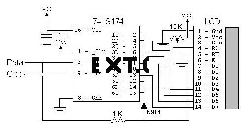
The most popular LCD interface is the Hitachi 44780 based LCD controller chip which provides a fairly easy to work with interface and low power consumption. The major drawback of the interface is the perceived complexity of working with...
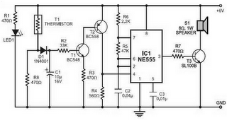
Fire alarm circuit using an LDR (Light Dependent Resistor) as a flame sensor. It warns the user about fire accidents by detecting smoke produced during a fire. As smoke passes between an LED and an LDR, the amount of...
This circuit is constructed around a 555 timer and utilizes very few components. Due to its simplicity, even beginners can easily assemble and use it as a control device. A readily available laser pointer can be employed to operate...
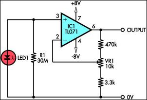
This circuit demonstrates the use of a standard LED as a light sensor by utilizing the photovoltaic voltage generated across the LED when it is exposed to light. LEDs are cost-effective alternatives to photodiodes and include a built-in filter...
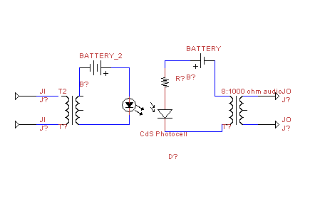
This circuit transmits audio information using light waves. It employs amplitude modulation (AM) to vary the intensity of an LED, which is detected by a cadmium sulfide photocell that changes its resistance based on light intensity. The circuit includes...
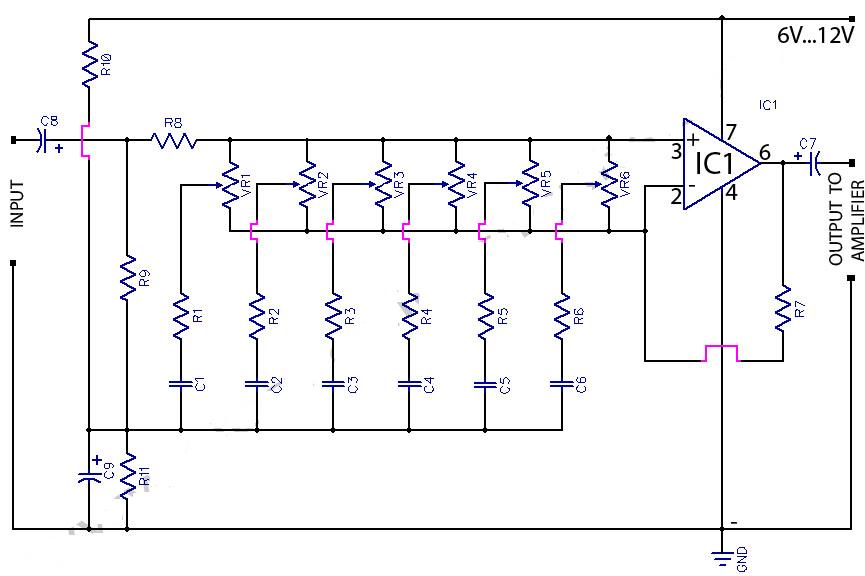
This circuit is a 6-band graphic equalizer that allows for the adjustment of low, medium, and high frequencies using the operational amplifier circuit 741. It enables control and mixing of frequencies and tones according to user preferences. The audible...