
Using LED As A Light Sensor

The circuit utilizes a red LED configured to operate as a photovoltaic device, generating a voltage in response to light exposure. The generated voltage is then fed into a TL071 JFET input op-amp, which is characterized by its high input impedance, making it suitable for amplifying the low-level signals produced by the LED. The choice of a TL071 op-amp is appropriate due to its low input offset voltage and high input impedance, which is crucial for accurately processing the small voltages from the LED.
Resistor R1 plays a critical role in establishing a baseline for the op-amp's input voltage, ensuring that it registers 0V in the absence of light. The selection of R1's value is a compromise between minimizing loading effects and ensuring that the op-amp can effectively amplify the signal without introducing significant error from its input offset. This careful balancing act is vital for maintaining the integrity of the light-sensing functionality.
The variable resistor VR1 allows for fine-tuning of the op-amp's gain, enabling the user to adjust the output voltage to match specific requirements based on the application's light conditions. This adjustability is particularly important in scenarios where varying light levels may be encountered, ensuring that the circuit remains responsive and accurate across a range of environmental conditions.
In summary, this circuit effectively transforms a common LED into a functional light sensor by leveraging its photovoltaic properties and amplifying the resulting signal with a high-performance op-amp, making it an economical and practical solution for light detection applications.This circuit shows how to use an ordinary LED as a light sensor. It makes use of the photovoltaic voltage developed across the LED when it is exposed to light. LEDs are cheaper than photodiodes and come with a built-in filter, which is useful when the application involves colour discrimination. The photo-voltage of a red LED (its bandgap voltage) is typically about 2V. The source impedance of this voltage is about 800M © in daylight, rising to infinity in darkness. A TL071 JFET input op amp is used to amplify and buffer this extremely high impedance signal. Resistor R1 ensures that the op amp "sees" a 0V input when the LED is in total darkness. To avoid undue loading of the signal, R1 would ideally be a 100M © or larger resistor but since such high values are rare and expensive I used a smaller value and increased the gain of the op amp to compensate for the voltage loss. To avoid the need for a second variable resistor to set the op amp`s input offset to zero, R1 must be large enough for the reduced voltage across the LED to swamp the op amp`s input offset voltage.
With a 30M © resistor for R1, the voltage at the op amp input when the LED is exposed to bright light is reduced to about 60mV. This is just over four times the 13mV maximum input offset of the TL071 op amp. R1 can be three 10M © resistors in series. Alternatively, I have found that a reverse-biased 1N4148 diode has an impedance of about 30M © (connect it in the circuit with the anode to ground).
The output of the circuit is about 0V when the LED is in darkness. VR1 sets the gain of the op amp and it should be adjusted to give the required output voltage when the LED is exposed to bright light. 🔗 External reference
Related Circuits
These small electronic lamps are quite practical and have a long lifespan. Approximately 40 years after Nick Holonyak invented the first LED, they have become nearly essential. Any dedicated electronics enthusiast typically keeps a few in their collection. Prior...

This is a simple automatic light switch circuit designed for bedrooms. After construction, connect the input terminals of this circuit in parallel to the existing light fixture. The automatic light switch circuit operates using a photoresistor (LDR) and a transistor...
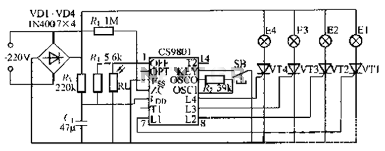
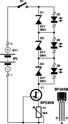
The ASIC is a flashing light string controller featuring four outputs. It includes a single key cycle control with six different lighting effects, and it allows for the selection of either 16 or 8 patterns. The circuit incorporates a...
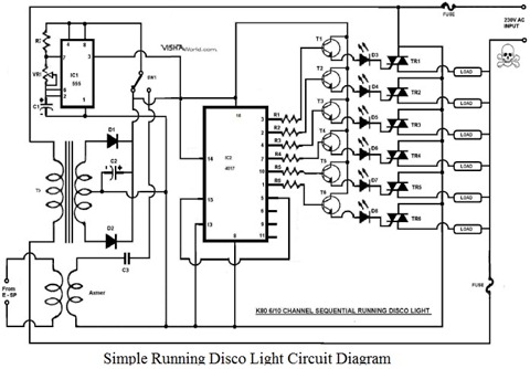
This article explains how to design a minimal Running Disco Light Circuit Diagram using the IC 4017. The IC 4017 is a 16-pin dual in-line package integrated circuit that includes a 10-stage decade counter. The design operates on 230V...
The 741 operational amplifier is configured as an audio oscillator utilizing Radio Shack 276-677 photocells within the feedback circuit. When light illuminates PC1, its resistance diminishes, leading to a corresponding decrease in the frequency of the audio tone heard...
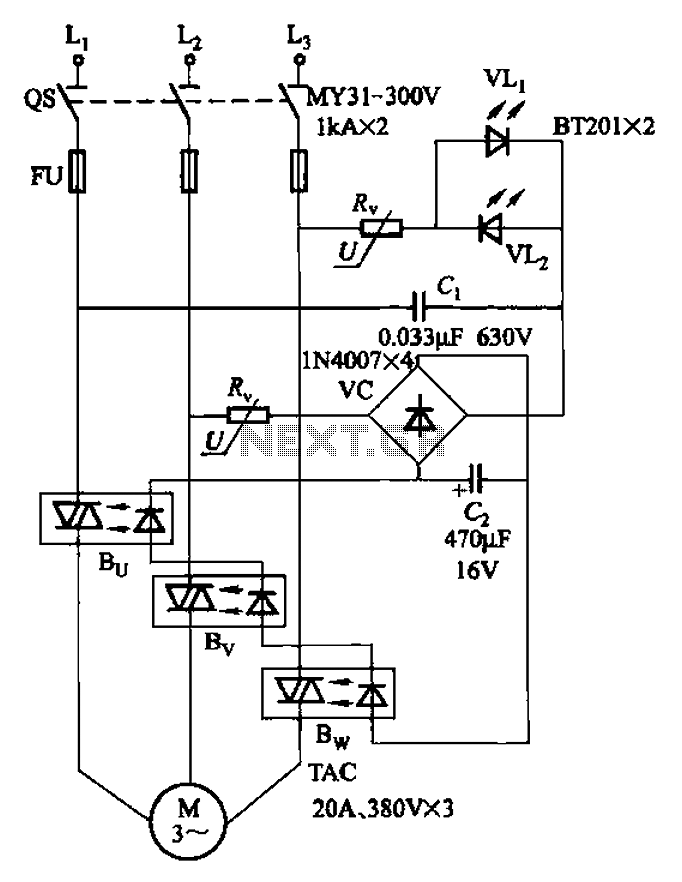
The circuit depicted in Figure 3-93 is integrated with an optical phase sequence protection relay. The circuit in question is designed to provide phase sequence protection using an optical relay mechanism. Optical phase sequence protection relays are crucial in applications...