
Audio 6 Band Graphic Equaliser Using 741 Op-Amp
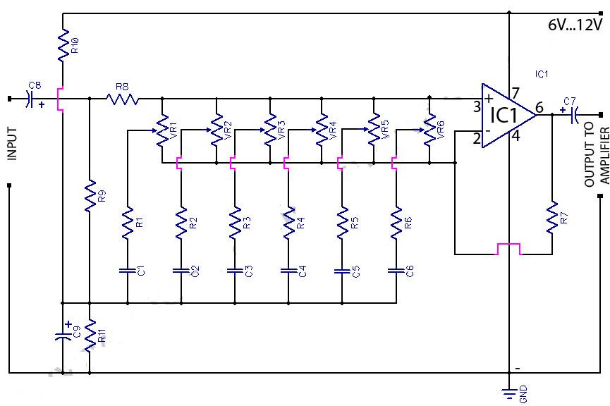
The 6-band graphic equalizer circuit utilizes a series of bandpass filters, each designed to target a specific frequency range. The operational amplifier (op-amp) model 741 serves as the core component for signal amplification and processing. Each of the six frequency bands is controlled by a linear potentiometer, allowing for precise adjustments to boost or attenuate the sound levels within the specified frequency ranges.
The frequency bands are typically centered around the following frequencies: 50Hz for low bass, 160Hz for mid-bass, 500Hz for lower midrange, 1.6kHz for upper midrange, 5kHz for presence, and 16kHz for brilliance. The choice of a linear potentiometer with a resistance of 100kΩ ensures smooth and predictable changes in the audio output, facilitating a user-friendly experience when fine-tuning sound.
The circuit's power supply can be conveniently derived from an associated amplifier or preamplifier, making integration into existing audio systems straightforward. The specified supply voltage range of 6V to 20V provides flexibility, allowing the equalizer to be used in a variety of applications without the need for a dedicated power supply. This adaptability, combined with negligible power consumption, makes the circuit suitable for both portable and stationary audio setups.
In practical applications, the graphic equalizer enhances audio playback by allowing users to tailor the sound to their preferences or to compensate for acoustic deficiencies in a given environment. The overall design promotes ease of use while maintaining high fidelity in audio reproduction, making it an essential tool for audio engineers, musicians, and audiophiles alike.This circuit is 6-band graphic equalizer, you can adjust the sound of low, medium and higher than the IC op amp circuit used 741. With this circuit you can control and mix of frequencies and tones to your liking. Audiblefrequency spectrum is covered in six steps: 50Hz, 160Hz, 500Hz, 1. 6kHz, 5kHz 16kHz, . All potentiometers are linear 100k ©. The ci rcuit provides adequate boost / cut for normal use. power supply for the circuit can be derived from the amp / preamp itself. The supply voltage range of rangeof (6V-20V) makes the circuit very versatile. Power consumption is negligible. 🔗 External reference
Related Circuits
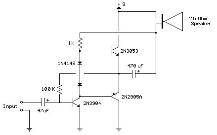
Improved 3 Transistor Audio Amplifier. The load resistor for the driver transistor is connected directly to the positive supply. This configuration has a disadvantage in that as the output moves positive, the voltage drop across... The improved three-transistor audio amplifier...
In this fire alarm circuit, a thermistor functions as the heat sensor. As the temperature rises, its resistance diminishes, and conversely, when the temperature falls, its resistance increases. At standard temperature, the resistance of the thermistor (TH1) is approximately...
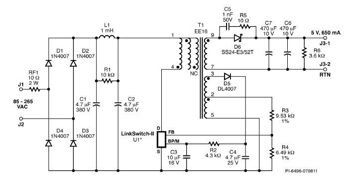
A simple 3.25W constant voltage/constant current (CV/CC) charger can be designed using the LinKSwitch family IC manufactured by Power Integrations. This electronic circuit project is intended to provide a 5-volt output with a maximum current of 650mA. The 3.25W...

Proper grounding is essential for eliminating hum and ground loops. The ground connections for J1, P1, C2, C3, and C4 should all be connected to the same point. Additionally, connect C9 to the output ground. In electronic circuits, grounding serves...
A sawtooth wave oscillator circuit can be implemented using several methods. Here, one design that employs the 555 integrated circuit is presented, along with its schematic diagram. The sawtooth wave oscillator utilizing the 555 timer IC operates in astable mode,...
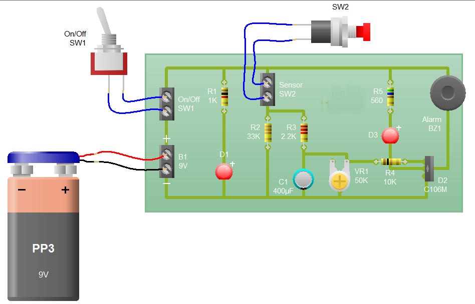
When the sensor switch SW2 is pressed, the LED D3 and the alarm are activated for a certain duration. The timing of the circuit is determined by the resistor R3 and capacitor C1. Additional details regarding the RC circuit...