
CMOS Toggle Flip Flop Using Laser Pointer circuit

The IR photo transistor Q1 serves as a critical component in the circuit, functioning as a light-sensitive switch. When the circuit is designed, it is important to position the photo transistor in a manner that minimizes exposure to ambient light. This can be achieved by using a housing or cover that blocks unintended light sources while allowing the desired laser light to reach the sensor.
In operation, under normal lighting conditions, the photo transistor will maintain a low output voltage at pin 6, indicating that it is in a non-conductive state. This low voltage is crucial for ensuring that any subsequent components in the circuit, such as microcontrollers or logic gates, interpret the signal correctly as an "off" state.
Upon exposure to a laser pointer or a similar light source, the photo transistor becomes conductive, allowing current to flow and causing the voltage at pin 6 to rise above 1 volt. This transition can be utilized to trigger other functions in the circuit, such as activating an alarm, turning on an LED, or sending a signal to a microcontroller for further processing.
To enhance the performance of the circuit, it may be beneficial to include additional components such as resistors for current limiting and capacitors for filtering. The choice of these components will depend on the specific requirements of the application, including the desired response time and sensitivity of the photo transistor to different light wavelengths. Proper calibration and testing will ensure that the circuit operates reliably under various lighting conditions.The IR photo transistor Q1 (Radio Shack 276-145A) or similar is connected to the set input (pin 6). The photo transistor should be shielded from direct light so that the voltage at the set input (pin 6) is less than 1 volt under ambient conditions and moves to more than volts when illuminated by the laser pointer or other light source.. 🔗 External reference
Related Circuits

This circuit is a bistable multivibrator, commonly known as a flip-flop. Activating the "set" input located at the lower left corner will raise the output to a high state (5V). Conversely, engaging the "reset" input at the lower right...
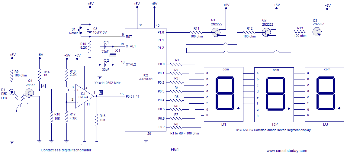
A three-digit contactless digital tachometer utilizing an 8051 microcontroller is presented for measuring the revolutions per second of rotating objects such as wheels, discs, or shafts. The tachometer can measure up to a maximum of 255 revolutions per second...

The HT6337 is an infrared remote control receiving decoder circuit specifically designed for electric fan applications. It is housed in a 28-pin dual-row DIP package, with the compatible model being HT12C. The HT6337 is part of a series of...

The TA8210AH integrated circuit (IC) is designed for use as an audio power amplifier in car audio systems. Typically, car audio setups include subwoofers and woofers, as the confined space of a vehicle does not require excessively high sound...
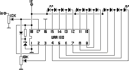
The NL3ASD schematic pages provide the schematics for a LED VU meter utilizing the UAA180 integrated circuit. The NL3ASD schematic pages feature a comprehensive design for a LED VU meter that employs the UAA180 IC, known for its audio signal...

This 5.1 surround amplifier circuit schematic utilizes the IC AN7168 as the primary component. The circuit requires a minimum voltage of 12V and a maximum voltage of 24V, with a recommendation of 12V due to the voltage ratings of...