
Bistable Multivibrator (Flip-Flop)
")
The bistable multivibrator circuit utilizes two NPN transistors, Q1 and Q2, configured in a feedback loop that allows for two distinct stable output states. The operation relies on the cross-coupling of the transistors, where the collector of Q1 is connected to the base of Q2 and vice versa. This arrangement creates a condition where the state of one transistor directly influences the state of the other.
When the "set" input is activated, a positive voltage is applied to the base of Q1, causing it to conduct. As Q1 turns on, its collector voltage drops, which in turn removes the base current from Q2. Consequently, Q2 turns off, and its collector voltage rises to near 5V. The feedback mechanism ensures that Q1 remains in the "on" state as long as the "set" input is activated.
Conversely, when the "reset" input is triggered, it applies a positive voltage to the base of Q2, turning it on. The resultant drop in collector voltage for Q2 allows current to flow into the base of Q1, switching it off. This transition reinforces the stability of the current state until the inputs are altered again.
This flip-flop design is commonly used in digital circuits for data storage, state retention, and as a basic building block in memory devices and sequential logic applications. The simplicity of the circuit allows for easy integration into larger systems, making it a fundamental component in electronics. The design can be enhanced with additional features such as debounce circuits for input stability or LED indicators to visually represent the output states.This circuit is a bistable multivibrator, or flip-flop. Click on the "set" input at lower left to bring the output high (5V). Click on the "reset" input at lower right to bring the output low (ground). The transistors are cross-coupled in such a way that the circuit has two stable states. Initially, Q2 is on and Q1 is off. Since Q1 is off, no curr ent is flowing through it, and its collector voltage is close to 5V. This allows current to flow through into the base of Q2, which keeps Q2 switched on. Q2 is in saturation mode, keeping the collector voltage close to ground; this prevents any current from flowing into the base of Q1 to switch it on. If you click the "set" input momentarily, this provides base current to Q1, switching it on, bringing its collector low, which stops the base current flowing to Q2.
So the circuit switches to the opposite state. Clicking the "reset" input switches back. 🔗 External reference
Related Circuits
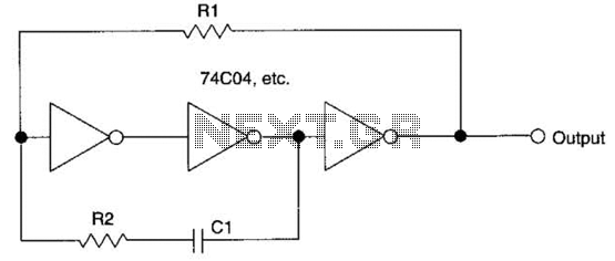
This circuit employs a protective resistor R2 along with a feedback resistor R1. Together, these components create a voltage divider that lowers the input voltage amplitude for IC1-a, ensuring that the protective diodes remain inactive. This arrangement enhances the...
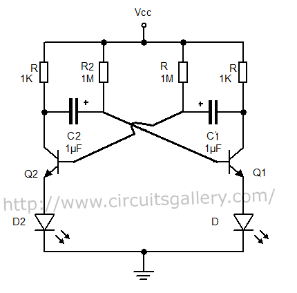
The output can also be taken from the collector terminals of the transistors, as illustrated in the circuit below. To understand the operation of the circuit, it is recommended to read about how a transistor functions as a switch. In...
Electronics tutorial about the 555 oscillator and how the 555 oscillator can be used as a 555 astable oscillator circuit to generate square wave waveforms. The 555 timer IC is a versatile and widely used component in electronics, particularly for...
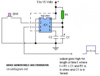
The following circuit illustrates a basic monostable multivibrator, which is based on the 555 Timer IC. Key features include pin 4 functioning as the RESET pin, with the time period defined by the equation t = R1 x C1. The...
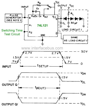
The pinout diagram for the 74L121 and 74L122 integrated circuits (ICs) is applicable to any style of 74xx121 or 74xx122 dual in-line package (DIP) chip, although the timing graphs are only relevant for the indicated TTL families. The 74121...
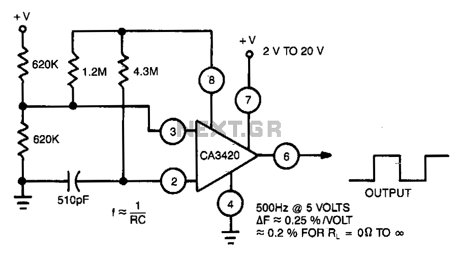
This multivibrator utilizes a CA3420 BiMOS operational amplifier to enhance frequency stability. The output frequency remains largely unaffected by supply voltage variations. Due to the inherent buffering action of pin 6, the frequency shift is approximately 0.2% when the...