
Code practice oscillator
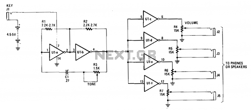
The circuit utilizes the 7404 hex inverter as its main amplification component, which is capable of transforming input signals into inverted outputs. The design begins with the activation of a switch that connects the battery to the circuit, ensuring a stable voltage supply of four to five volts. This voltage is crucial for the operation of the 7404, enabling it to amplify signals from various transducers effectively.
In the initial stage, the first two inverter amplifiers, Ula and Ulb, receive their biasing through resistors Rl and R2. These resistors establish a feedback mechanism that stabilizes the input signal for optimal performance. The feedback loop is further enhanced by the combination of the capacitor (C1) and rheostat (R3), which not only fine-tunes the phase of the output signal but also helps in managing the frequency response of the circuit.
As the signal passes through Ulb, it is then transmitted to the subsequent inverter amplifiers, Ulc to Ulf. This cascading configuration allows for greater amplification of the audio signal, which is essential for driving output devices such as headphones or speakers. The final audio output is controlled through the volume control potentiometers (R4-R7), which can be adjusted to suit the user’s preference. The selection of potentiometer values is flexible, ranging from 1500 ohms to 10,000 ohms, with lower resistance values being particularly advantageous for applications involving speakers or low-impedance headphones. Overall, this circuit design exemplifies a robust and versatile approach to audio amplification using the 7404 hex inverter.The inexpensive 7404 hex-inverter has enough amplification to handle a wide range of transducers. Closing the key completes the battery circuit and applies four to five volts to the 7404. Bias for the first two inverter amps (Ula and Ulb) comes from the two resistors, Rl and R2, connected between their inputs and outputs. The capacitor and rheostat (R3/C1) close the feedback loop from the input to the properly-phased output.
The signal leaving Ulb drives the remaining four inverter amplifiers, Ulc through Ulf; they, in turn, drive the phones or speakers. The volume control potentiometers, R4-R7, may have any value from 1500 ohms to 10,000 ohms. The smaller values work best when speakers, or low impedance phones, are used. 🔗 External reference
Related Circuits
The particular circuit does not have the requirement to replace the trade decoders Surround, because they have many more facilities and possibilities. It gives, however, the possibility in many trials with this article of decoding. The coding in Stereo...
Generating variable audio frequencies with crystal precision is challenging due to the scarcity of low-frequency quartz crystals, which typically produce a single frequency. While minor adjustments to the frequency of a crystal oscillator can be made using a trimmer...
500 Series immersion temperature probe, NTC, 100,000 Ohm, ±1.5 °C [±2.7 °F] tolerance, 10 °C to 260 °C [50 °F to 500 °F] accuracy, stainless steel, bullet housing, flying leads (two), 26 gauge Teflon insulation, 4,267 mm [168 in]. The...
The decoder is intended to be a reference quality prototype with maximum flexibility for experimental use with different speaker layouts. A new improved version has been added at the end. There are two main sections to the instrument. The...
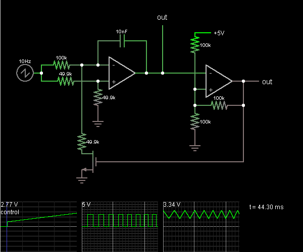
This circuit is a voltage-controlled oscillator, which is an oscillator whose frequency is determined by a control voltage. A 10 Hz sawtooth oscillator provides the control voltage in this case; this causes the frequency to rise slowly until it...
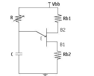
At the point Vp, the emitter triggers and turns the UJT (Uni-Junction Transistor) ON. Up to this point, the emitter is isolated and does not conduct, resulting in no current conduction between Base1 and Base2. The operation of the Uni-Junction...