
Surround Sound Decoder


The circuit described is a multi-channel audio processing system designed to decode and manage audio signals for surround sound applications. The architecture employs operational amplifiers (op-amps) for signal buffering and amplification, notably using the TL072 and TL074 series for their low noise and high performance in audio applications.
The initial stages of the circuit utilize IC1A and IC1B as input buffers for the left and right channels, respectively. This configuration ensures that the stereo signals are adequately prepared for subsequent processing without introducing significant distortion or noise. The summing amplifier IC2C combines these two channels, producing a central channel output that is essential for a cohesive surround sound experience.
Following this, the differential amplifier IC2D processes the difference between the left and right channels, effectively isolating the phase information necessary for driving rear loudspeakers. This phase information is crucial for creating the spatial effects characteristic of surround sound systems.
A delay unit, realized with IC5, introduces a controlled delay to the rear channels, enhancing the perception of depth and spatial orientation in the audio. The delay is adjustable via a variable capacitor (C17), allowing for customization based on the acoustics of the listening environment. This aspect of the design is particularly important, as it accounts for variations in room size and speaker placement.
Filters surrounding IC6A/B are implemented to manage frequency response, ensuring that only the necessary bandwidth (100Hz to 8kHz) is passed to the rear loudspeakers. This filtering is essential to prevent unwanted high-frequency noise and low-frequency rumble from reaching these speakers, thus optimizing their performance.
The circuit's power supply is designed to provide a symmetric voltage of ±15V, which is critical for the operation of the op-amps and ensures stable performance across the audio spectrum. The inclusion of potentiometers at the outputs allows for fine-tuning of the output levels, facilitating integration with external power amplifiers and loudspeakers.
The comprehensive design and component selection in this circuit reflect a thoughtful approach to achieving high-quality audio processing for surround sound applications, making it suitable for various home theater and professional audio setups. The particular circuit does?t have the requirement to replace the trade decoders Surround, because this they have many more facilities and possibilities. It give however the possibility in many try with this article of decoding. The coding in Stereo Dolby Surround show the tendency to be abandoned and is replaced with digital DTS, Dolby 5.1 etc, that is supported in the digital level of management and transport, sound signal.
In order that appears also in the Fig.2, the stereo sound signal that transport the surround information, is drive for the Lch in the IC1A and Rch in the IC1B, that is input buffer with the next stages. Then follow the stages of summing [ IC2C ], which add up the signals of channels L+R and him drive to the output for central loudspeaker and a differential amplifier [ IC2D ], that rise the difference of phase L-Rch with which is written in the two channels, the information for Rear loudspeakers. The exit of IC2D drive one regulated delay unit of sound to Rear loudspeakers, so that are created the sense of space and her adaptation in the size of our own room.
It?s constituted by the IC5, that is a opamp. sound delay signal of 512 stages. The timing of IC5 becomes from the IC4, that is a oscillator. The delay time is regulated by variable capacitor C17. In order to we cut the noise that is produced by this process exist certain filters then, regulated they cut the frequencies above 8KHZ and under 100 HZ roughly, after we behind did ?t need bigger frequencies bandwidth, to drive the Rear loudspeaker. The Rear information is written with bandwidth of 100HZ until 8KHZ, for this reason Rear loudspeaker has small size.
These filters are found round the IC6A/B, that is output buffer, too. In all the outputs exist potesometer that help in the right level regulation of amplifiers and loudspeakers, that follows. Obvious it?s that each exit should drive single power amplifier .The circuit is supplied by symmetric voltage ± 15V.
Part List R1-2-7-8-12-13-18-19-20=47Kohm C11-12-15=10uF 25V RV1-RV2=2X10Kohm Log. pot. R3-4-5-6-21-22-34-35=10Kohm C13=82nF RV3-4=10K Log pot. R9-10-11-14-15-16-17=15Kohm C16=18pF 100V D1=1N4148 R=23-24-25-33-36=100ohm C17=100pF mini adjustable capacitor IC1-6=TL072 R26-27-28-31-32=100Kohm C18=2.2nF IC2-3=TL074 R29-30=5.6Kohm C19=4.7uF 25V IC4=MN3101 C1-8=47uF 25V C20=100nF 100V IC5=MN3004 C2-7-9-14-23=47nF 100V C21=10nF JI.....J6=RCA female jack C3-6=1uF 100V C22=180pF C4-5-10=33pF 100V C24=150nF 🔗 External reference
Related Circuits
The schematic diagram of the MS Decoder may appear complex, but it is relatively straightforward. Initially, both the Mid and Side signals are buffered using unity gain inverting buffers, which are constructed around IC1b and IC2b. This buffering serves...
This simple circuit, as shown in the schematic diagram, activates a switch using sound. It can be utilized for various applications, such as automatic sound-controlled disco lights or a car's LED light show. The transistor Q1 amplifies the audio...
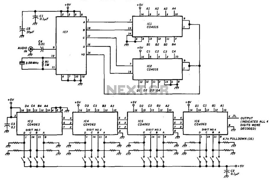
This decoder will respond to a preselected 4-digit DTMF number. IC7 is a Radio Shack IC device (part #276-1303). The logic is all CMOS. The digits are selected by SW1 and SW2, a pair of 8-position DIP switches. The described...
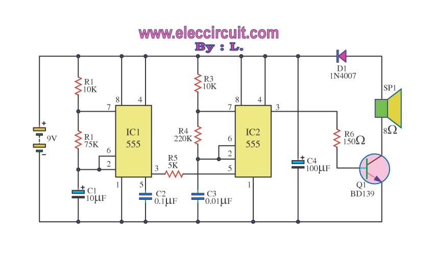
Many people might be excited by the sound of a siren, as it is often associated with emergency events such as accidents. However, one may wonder about the underlying mechanisms that produce this alerting sound. The siren sound commonly used...
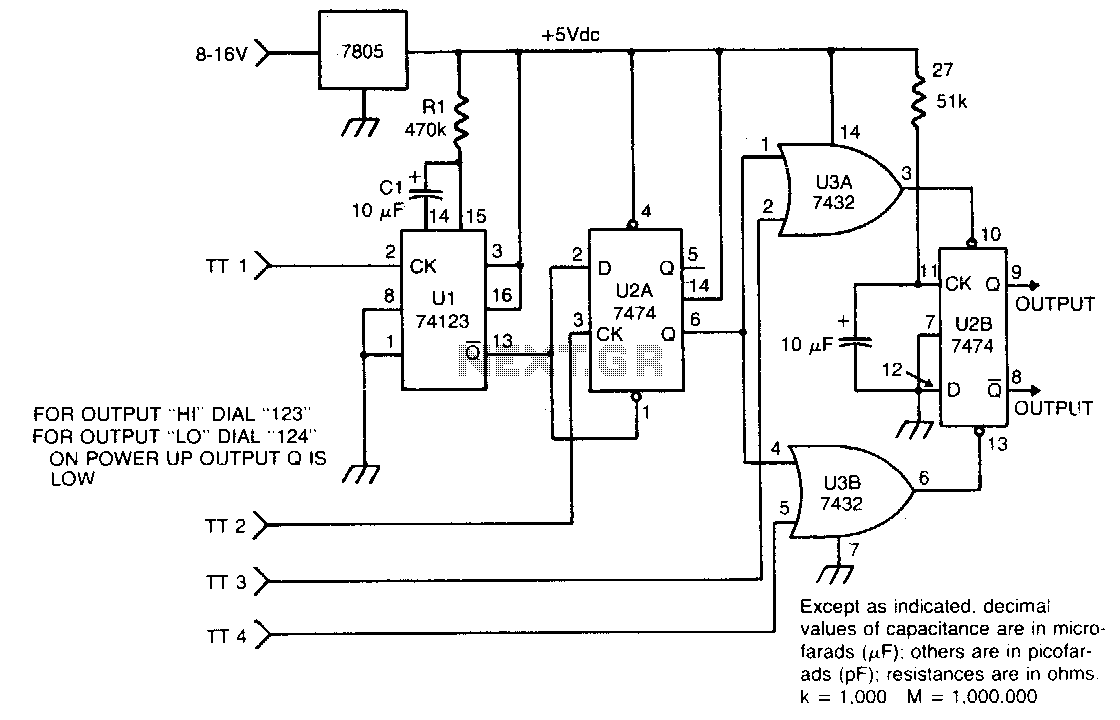
The circuit takes active low inputs from a Touch Tone decoder and reacts to a proper sequence of digits. The proper sequence is determined by which Touch Tone digits the user connects to the sequence decoder inputs TT1, TT2,...
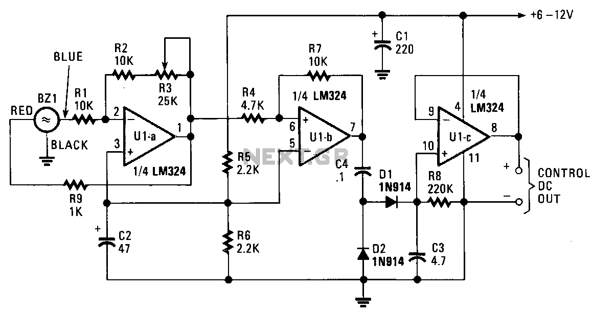
The piezo transducer functions as both a sound pickup device and a frequency-selective filter. By adjusting the gain of the operational amplifiers (op-amps), the oscillator can be configured as a sensitive and frequency-selective tone decoder circuit. When the gain...