
Code-Practice Oscillator Iii

The described circuit is a simple tone generator utilizing a silicon-controlled rectifier (SCR) and a capacitor in conjunction with a potentiometer for frequency modulation. The capacitor CI serves as the energy storage component, charging through resistor R1. The charging process continues until the voltage across CI reaches a predetermined threshold set by potentiometer R2, which acts as a variable resistor to adjust the gate voltage of the SCR.
Once the gate voltage reaches the necessary level, the SCR is triggered into conduction. This allows current to flow through the SCR, powering the connected earphones and discharging the capacitor. The discharge of CI results in a rapid drop in anode voltage and current, which leads to the SCR turning off and stopping the current flow. This process creates a pulsing effect that can generate sound when using the earphones, as they convert the electrical pulses into audible tones.
The frequency of the generated tone can be adjusted by varying the resistance of potentiometer R2, which modifies the charge time of the capacitor CI. A lower resistance results in a quicker charge and discharge cycle, producing a higher frequency tone, while a higher resistance slows down the cycle, resulting in a lower frequency tone. The circuit is powered by a 9-V battery, with the telegraph key acting as a switch to control the power supply to the circuit.
This configuration is particularly suited for applications in simple sound generation, educational projects, or as a basic audio signal generator. The use of standard 8-ohm headphones allows for easy sound output, making the circuit user-friendly and accessible for experimentation. Capacitor CI charges through resistor Rl, and when the gate level established by potentiometer R2 is high enou gh, the SCR is triggered. Current flows through the SCR and earphones, discharging CI. The anode voltage and current drop to a low level, so the SCR stops conducting and the cycle is repeated. Resistor R2 lets the gate potential across CI be adjusted, which charges the frequency or tone. Use a pair of 8- headphones. The telegraph key goes right into the B + line, 9-V battery.
Related Circuits
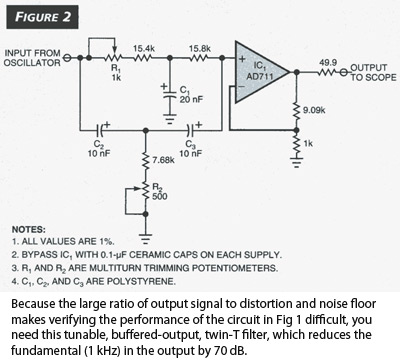
The Wien-bridge sine-wave oscillator utilizes a light bulb for amplitude stabilization. The circuit depicted in Fig 1 omits the light bulb and incorporates several enhancements that reduce distortion and produce a test signal sufficiently pure for evaluating modern operational...
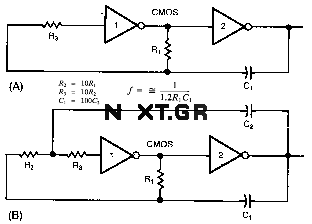
The common clock oscillator illustrated in Fig. 68-19A has two minor issues: it may not oscillate if the transition regions of its two gates differ. If it does oscillate, it might occasionally operate at a slightly lower frequency than...
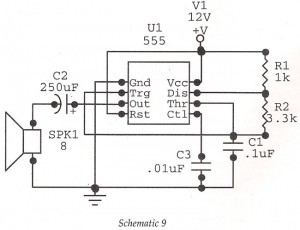
This circuit features an astable oscillator constructed around a 555 timer, generating an alarm tone of 1.8 kHz, which directly drives a speaker. It serves as a fundamental alarm circuit that can be utilized in various projects. Although the...
In Japan, the household electricity operates at either 50 Hz or 60 Hz. For a frequency of 50 Hz, one complete sine wave occurs 50 times in one second, while at 60 Hz, it occurs 60 times. Lissajous figures...
One example of the phase shift oscillator is the Bubba oscillator. This oscillator achieves a 45-degree phase shift for each section from a quad op-amp package. The Bubba oscillator is a type of phase shift oscillator that utilizes a...
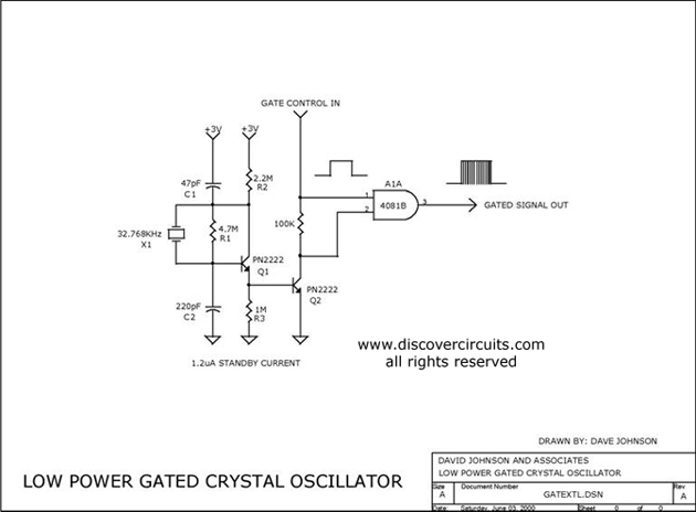
The circuit controls the output of a continuously operating 32KHz crystal oscillator, directing it to the input of a C-MOS buffer when clock pulses are required. This technique addresses the issue of a slow-starting crystal oscillator by maintaining the...