
Code Practice Oscillator Using 555 Timer
The circuit employs a 555 timer configured in astable mode, which allows it to generate a square wave output. This output frequency can be adjusted to create the distinct sounds associated with Morse Code. The circuit consists of a few key components: the 555 timer IC, resistors, capacitors, and a push-button switch.
When the push-button switch is pressed, it activates the 555 timer, causing it to oscillate at the predetermined frequency. The frequency of the output signal can be controlled by varying the resistor and capacitor values in the timing circuit. A typical configuration might use a resistor in the range of 1kΩ to 10kΩ and a capacitor of around 10µF to 100µF. This combination will generate the desired frequencies for "dit" (short beep) and "dah" (long beep) sounds.
To ensure the output is audible, the 555 timer is connected to a small speaker or piezo buzzer. The audio output can be further amplified if necessary, depending on the application and the desired volume level. A simple low-pass filter may also be added to smooth out the output waveform, reducing harmonics and providing a cleaner sound.
The circuit can be powered by a standard 9V battery or a DC power supply, making it portable and easy to use in various environments. This project not only serves as a practical introduction to the 555 timer and basic electronics but also provides a fun way to learn Morse Code through auditory signals.This simple code practice oscillator project for beginners to Continuous Wave Morse Code uses a 555 timer to generate a dit or dah sound when the key is pressed 🔗 External reference
Related Circuits
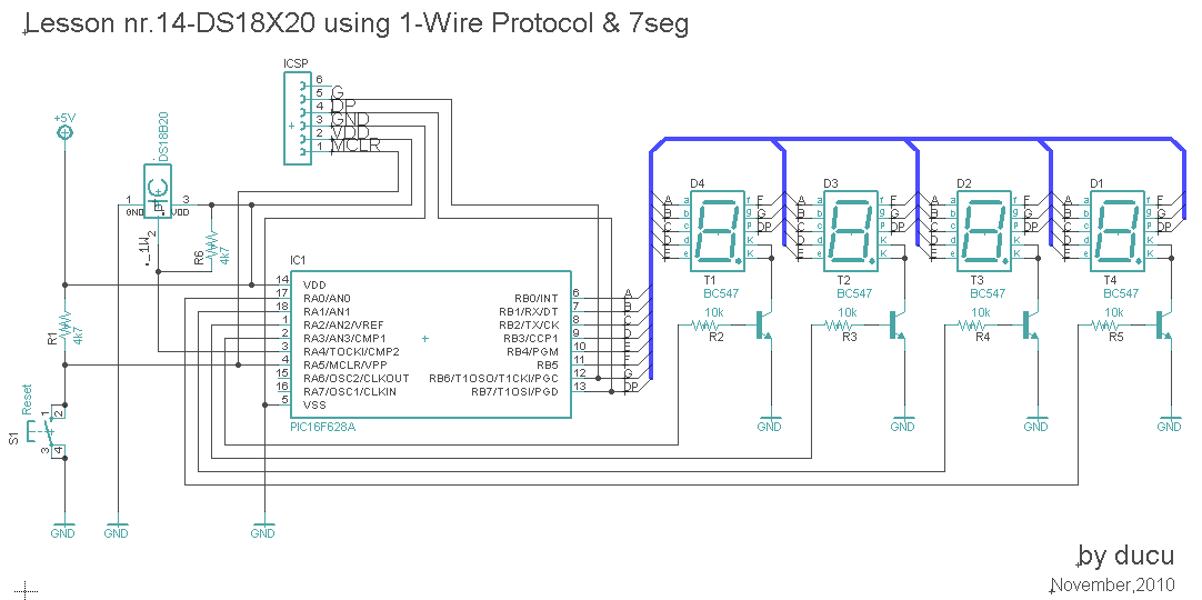
In this lesson, a digital temperature meter will be constructed using the DS18B20 temperature sensor. The connection between the temperature sensor and the microcontroller will utilize a single wire, which is a significant advantage of this sensor model. The...
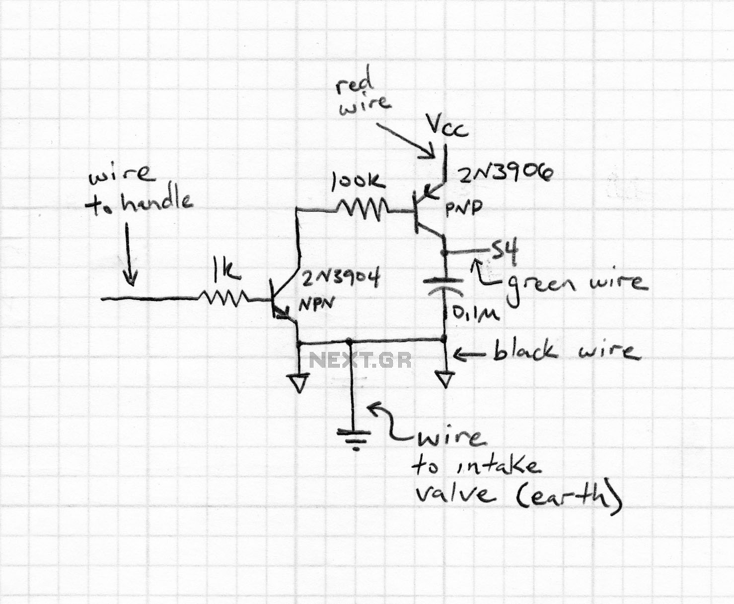
The purpose of this experiment is to explore the properties of a nonlinear circuit that closely resembles a driven pendulum. This serves as an excellent introduction to nonlinear phenomena, including period doubling and chaos. The circuit presented is an...
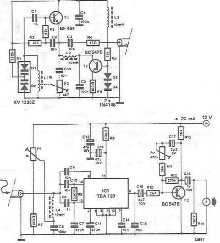
The tuning stage of this long-wave and medium-wave radio receiver also functions as an active antenna, which can be optimally positioned for the best reception. The circuit is completely independent from the receiver, which includes a demodulator that provides...
The market offers numerous devices that replace traditional wall switches, allowing for the adjustment of bulb luminosity. For those looking to create an "intelligent" home or a more complex device for controlling light bulb power, several options are available....
The two circuits below illustrate the application of the 555 timer to activate a relay for a specified duration by pressing a momentary normally open (N/O) push button. The circuit on the left can be used for longer time...
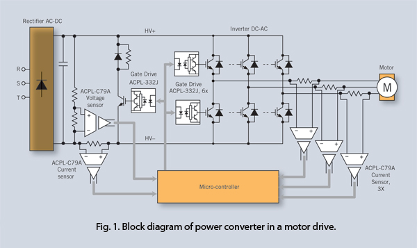
Isolation amplifiers provide an effective method to protect IGBTs against over-current, overload, and overvoltage conditions in addition to their current/voltage sensing function. Using these devices together with feature-rich gate drivers, a cost-effective yet comprehensive IGBT protection scheme can be...