
Coffee thermometer circuit

Measuring the temperature of coffee can be accomplished using a simple electronic circuit designed to provide accurate readings. A typical setup may include a thermistor or a thermocouple as the temperature sensor, which converts the temperature into an electrical signal. This signal can be processed by an operational amplifier (op-amp) to enhance its strength and accuracy.
The circuit can be designed to include an analog-to-digital converter (ADC) for digital output, allowing for easy integration with microcontrollers or digital displays. The microcontroller can be programmed to interpret the ADC readings and display the temperature on an LCD screen or send it to a smartphone via Bluetooth for remote monitoring.
Power management is also a crucial aspect of the design. A power supply circuit, which may include a voltage regulator, ensures that the sensor and microcontroller receive a stable voltage. Additionally, incorporating a battery management system can extend the operational life of the device.
To enhance user experience, the circuit can include features such as temperature alerts or the ability to log temperature data over time, providing insights into how temperature variations affect coffee flavor profiles. Overall, the electronic schematic for measuring coffee temperature consists of a temperature sensor, signal processing components, a microcontroller, and a display or communication module, all working together to ensure precise temperature measurement and data management.Why measure the temperature of the coffee? Well, coffee taste depends on two things. First, how strong the coffee is and second, how hot it is. The second. 🔗 External reference
Related Circuits
VOX is a voice-activated switch commonly used with microphones as an alternative to traditional push-button switches. The VOX can be connected to various audio equipment featuring an external speaker for coupling. The activation threshold is adjusted using the volume...
A small circuit that can find a lot of applications for measuring time. It has the capability to inform with a sound signal from the BZ1. At the same time, there exists the possibility to drive an external circuit...
The circuit schematic is straightforward. Information regarding the assembly and testing of circuits is not provided, as there are many instructional resources available. The circuit schematic in question is designed to be simple and user-friendly, allowing for ease of understanding...
These accessories are low-cost, high-speed, bifet-input operational amplifiers utilizing internally compensated voltage (BI-FET II technology). They require low supply voltages while offering a wide gain bandwidth product and fast slew rate. Additionally, well-matched high voltage JFET input devices accommodate...
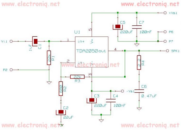
The TDA2050 integrated circuit can be used to design a simple high-fidelity audio power amplifier, intended for use as a Class AB audio amplifier. Due to its high power capabilities, the TDA2050 audio power amplifier can deliver up to...
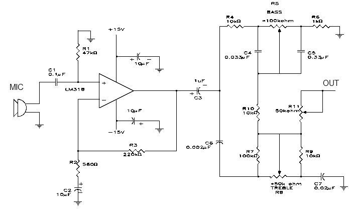
This simple microphone preamplifier is based on the LM318 operational amplifier. The LM318 operates as a standard non-inverting amplifier. Resistor R1 provides a ground input path for the bias current of the non-inverting input. The combination of R2 and...