
Timer Circuit with optocoupler

TIME SET TABLE
RV1 C2 TIME
500K 220nF 1min-30min
500K 470nF 1min-60min
1M 470nF 1min-120min
Part List
R1=2.2MΩ C1=10nF 100V MKT IC1=4060
R2=18KΩ C2=220nF 100V MKT (see table) IC2=4N25
R3=1MΩ RV1=500KΩ pot. (see table) BZ1=buzzer
R4=1.2KΩ D1=LED RED B1=9V Battery or ext. pack supply
R5-6-7=1KΩ Q1-2=BC547 S1=ON-OFF mini Switch
The described circuit serves as a versatile timer with sound output and external control capabilities. The core of the circuit is the 4060 IC, which integrates an oscillator and a 14-stage binary divider. The oscillator's frequency is adjustable through a resistor-capacitor (R-C) network connected to specific pins, allowing for a range of timing applications.
The reset function is crucial for initiating the timing sequence, achieved by applying a pulse to the reset pin through the capacitor C1 and resistor R3. This ensures that every timing session starts from zero. The output Q14 signals the completion of the timing interval, activating the transistors Q1 and Q2, which in turn energize the buzzer BZ1 to provide an audible indication of the elapsed time. The optocoupler IC2 allows for the isolation and control of external circuits, enhancing the circuit's functionality in various applications.
The time delay can be finely tuned using the potentiometer RV1 in conjunction with the capacitor C2, as detailed in the provided time set table. This flexibility enables users to select timing intervals that suit their specific requirements, ranging from short durations to extended periods.
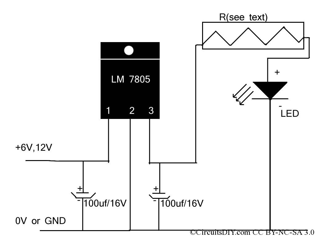
Power supply options include a 9V battery or an external power source, providing convenience for portable or stationary use. The LED D1 serves as a visual indicator of circuit operation, while its removal does not compromise the circuit's functionality. Current consumption during operation remains low, making this circuit efficient for prolonged use. However, care should be taken to account for increased current demands when the output is activated, ensuring that the power supply can accommodate the load. Overall, this circuit demonstrates a practical approach to time measurement and control in electronic applications.A small circuit that can find a lot applications of measurement time. She has the possibility us inform with sound signal from the BZ1. At the same time, exist the possibility drive a external circuit via the optocoupler IC2, after we connect the applicable circuit in contacts [ A ] and [ B ]. The circuit is based on IC1 (4060), which include in his inside, oscillator and a binary divider of 14 stage.
The frequency operation of oscillator is determined by a circuit R-C that connected in pins 9,10,11 of IC1. We give supply in the circuit, with switch S1, is presented a pulse in 12 [ RESET ] via C1 and R3, null him counter, require the measurement of pulses to begin from the zero.
Than the count get at in 14th digit then exit Q14 in the pin 3, acquire high logic level. This voltage drive the base the Q1-2, the transistors turn on, thus buzzer BZ1 sound, also the IC2 is ready to drive, via contacts [ A][B ], any suitable external circuit. The time delay is regulated with the potesometer RV1, in time delay that begin from 1 minute up to 2 hours, proportionally with the combination of prices that they will have the RV1 and C2.
[ see Table ]. The circuit can be supplied from a battery 9V or from external supply. Led D1 and R4, we can him cut out, they do not affect the circuit, simply us it show that the circuit work. The requirement in current when the circuit make time count, are not big (1mA roughly), with the D1 in circuit, on the contrary when activated output Q14, then the requirements in current boost, proportionally the materials that are activated [ D1, BZ1, IC1 ], reaching roughly 40mA..
TIME SET TABLE RV1 C2 TIME 500K 220nF 1min-30min 500K 470nF 1min-60min 1M 470nF 1min-120min Part List R1=2.2Mohm C1=10nF 100V MKT IC1=4060 R2=18Kohm C2=220nF 100V MKT (see table) IC2=4N25 R3=1Mohm RV1=500Kohm pot. (see table) BZ1=buzzer R4=1.2Kohm D1=LED RED B1=9V Battery or ext. pack supply R5-6-7=1Kohm Q1-2=BC547 S1=ON-OFF mini Switch 🔗 External reference
Related Circuits
If the reader arrived here via Google, they may have encountered other circuits for high-power LED driving that include many components such as inductors, operational amplifiers, various regulator ICs, transistor feedback networks, and microcontrollers. While those circuits tend to...
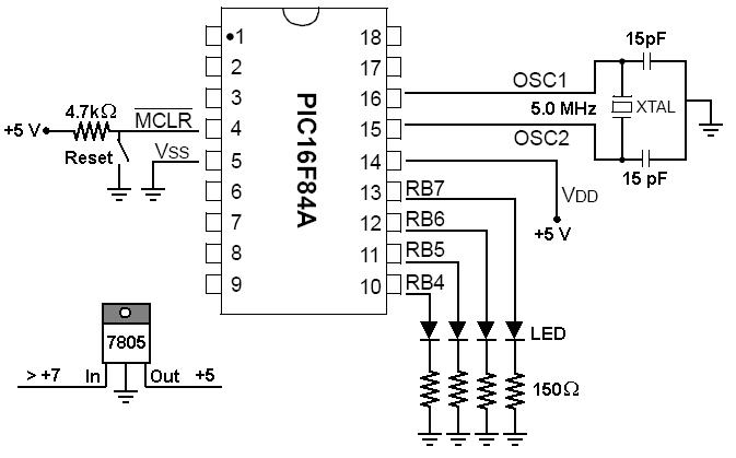
To start working with microcontrollers, several essential items are required. The PICSTART Plus kit, part number DV003001, was purchased from Microchip. This kit contains a sample PIC16F84 microcontroller chip, which in this case is a PIC16F84A chip. This chip...
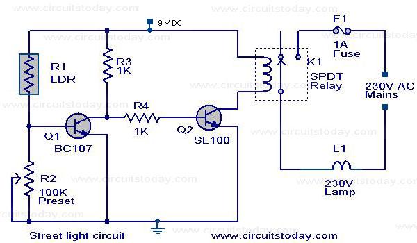
The circuit diagram of an Automatic Street Light Controller Circuit is explained in this post. The Automatic Street Light Controller Circuit is designed to automatically turn on street lights at dusk and turn them off at dawn. This functionality is...
The video amplifier depicted in the diagram is a widely recognized design that is both simple and highly effective. However, the transistors are susceptible to damage if the potentiometers (black level and signal amplitude) are set to their extreme...
The gain of the single-stage virtual earth amplifier IC1 is determined by the drain-source resistance of the field-effect transistor (FET). Resistors R1, R2, and R3 linearize the FET's voltage-current characteristic. A control voltage is derived from the output signal...
The Digital Combination Lock Circuit is a schematic for a simple electronic combination lock utilizing the LS7220 integrated circuit (IC). This password-protected digital lock can activate a relay to control any device by entering a preset combination of four...