
Coilless FM Transmitter
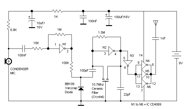
The RF oscillator circuit is designed to generate a stable radio frequency signal at 10.7 MHz, which is commonly utilized in various communication applications. The core component, inverter N2, functions as the oscillator, producing a square wave output. This output is then filtered by the 10.7 MHz ceramic filter to eliminate unwanted frequencies and harmonics, ensuring a cleaner signal.
Inverters N4 to N6 are configured in parallel, which serves to decrease the overall output impedance of the circuit. This low impedance is crucial for effectively driving a 1/4 wavelength aerial, which is typically used for efficient radiation of the RF signal. The choice of a 1/4 wavelength aerial is advantageous as it allows for optimal performance in terms of radiation efficiency and bandwidth.
The square wave output from the inverters N4 to N6 inherently contains multiple harmonics. While the fundamental frequency is at 10.7 MHz, the square wave nature of the signal results in the generation of odd harmonics, including the 9th harmonic. These harmonics can be both beneficial and detrimental, depending on the application. In some cases, they may be utilized for frequency multiplication or other signal processing tasks, while in other situations, they may need to be filtered out to avoid interference with adjacent frequency channels.
Overall, this RF oscillator circuit design demonstrates effective use of inverters and filtering techniques to achieve a desired frequency output, with considerations for impedance matching and harmonic content management, making it suitable for various RF applications.The RF oscillator using the inverter N2 and 10.7Mhz ceramic filter is driving the parallel combination of N4 to N6 through N3.Since these inverters are in parallel the output impedance will be low so that it can directly drive an aerial of 1/4th wavelength. Since the output of N4-N6 is square wave there will be a lot of harmonics in it. The 9th harmonics o.. 🔗 External reference
Related Circuits
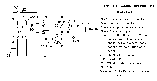
The circuit is a common form used in FM transmitters. The transistor conducts for 60-90 electrical degrees. When it turns off the LC tank rings, completing the sinusoidal waveform coupled to the antenna. The circuit is 77-85% efficient, compared...
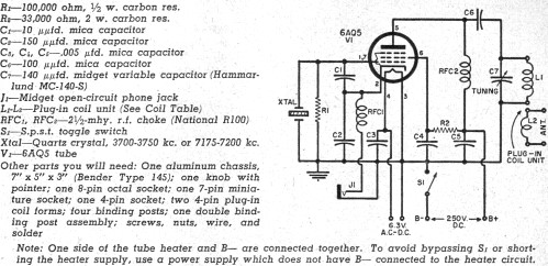
Although this CW transmitter circuit was published in 1955 in Popular Electronics, it remains legal for today's amateur radio operators. Portions of the 40-meter and 80-meter bands are still reserved exclusively for CW operation. As of 2011, the frequencies...
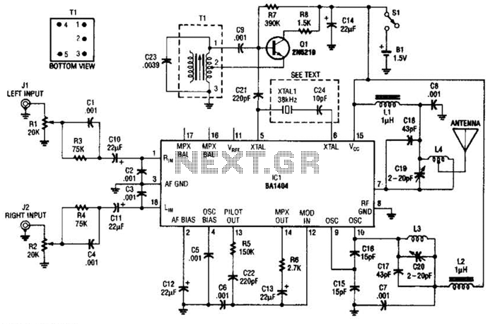
In this application, a BA1404 is utilized to generate an FM MPX baseband signal. This signal modulates a crystal oscillator (Q3) through a dual varactor series modulator. This transmitter can be used to play CD audio on an existing...
Wireless headphone transmitter and receiver systems are now widely available in the market, offering a variety of pricing options along with reliable technical specifications for various applications. These include wireless headphones for televisions, computers, and earbuds. A wireless headphone...
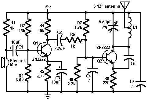
This circuit is a simple two-transistor (2N2222) mini FM transmitter. No authorization is required for this transmitter according to FCC regulations regarding wireless microphones. When powered by a 9-volt battery and equipped with an antenna no longer than 12...
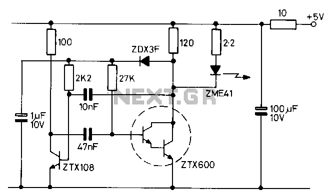
The transmitter consists of an oscillator that drives a high-output infrared (IR) emitting diode. The oscillator is a simple multivibrator circuit that provides an output with a mark-to-space ratio ranging from 15 to 1000 at a frequency of 1...