
COLLEGE QUIZ BUZZER
The circuit design effectively addresses the common challenges faced in quiz competitions by providing a reliable and cost-effective solution for identifying the first responder among multiple participants. The use of the 74LS373 octal latch allows for efficient data handling, ensuring that only one contestant's input is registered at any given time. This is crucial in competitive environments where timing is essential.
The power supply section's design ensures stable operation of the entire circuit by converting high voltage AC mains into a safe, regulated DC voltage suitable for digital logic circuits. The transformer not only steps down the voltage but also provides electrical isolation, enhancing safety. The rectification and filtering stages are critical for removing any AC ripple, ensuring that the voltage regulator receives a clean input.
In the quiz buzzer section, the design allows for straightforward integration of push-to-on switches, making it user-friendly. The arrangement of the torch bulbs in easily identifiable boxes enhances visibility, ensuring that both participants and the audience can quickly recognize the active contestant. This attention to detail in the physical layout contributes to the overall effectiveness of the circuit in a live quiz setting.
The inclusion of SCRs for controlling the bulbs adds robustness to the design, allowing for higher current handling without stressing the controlling logic. The piezo buzzer serves as an auditory signal, providing immediate feedback to the contestants and audience, further enhancing the competitive atmosphere.
Overall, this circuit design is a practical solution for quiz competitions, combining simplicity, effectiveness, and cost-efficiency.Manual buzzers used for quiz competitions in schools and colleges create a lot of confusion in identifying the first respondent. Although there are circuits using PCs and discrete ICs, they are either too expensive or limited to only a few number of players.
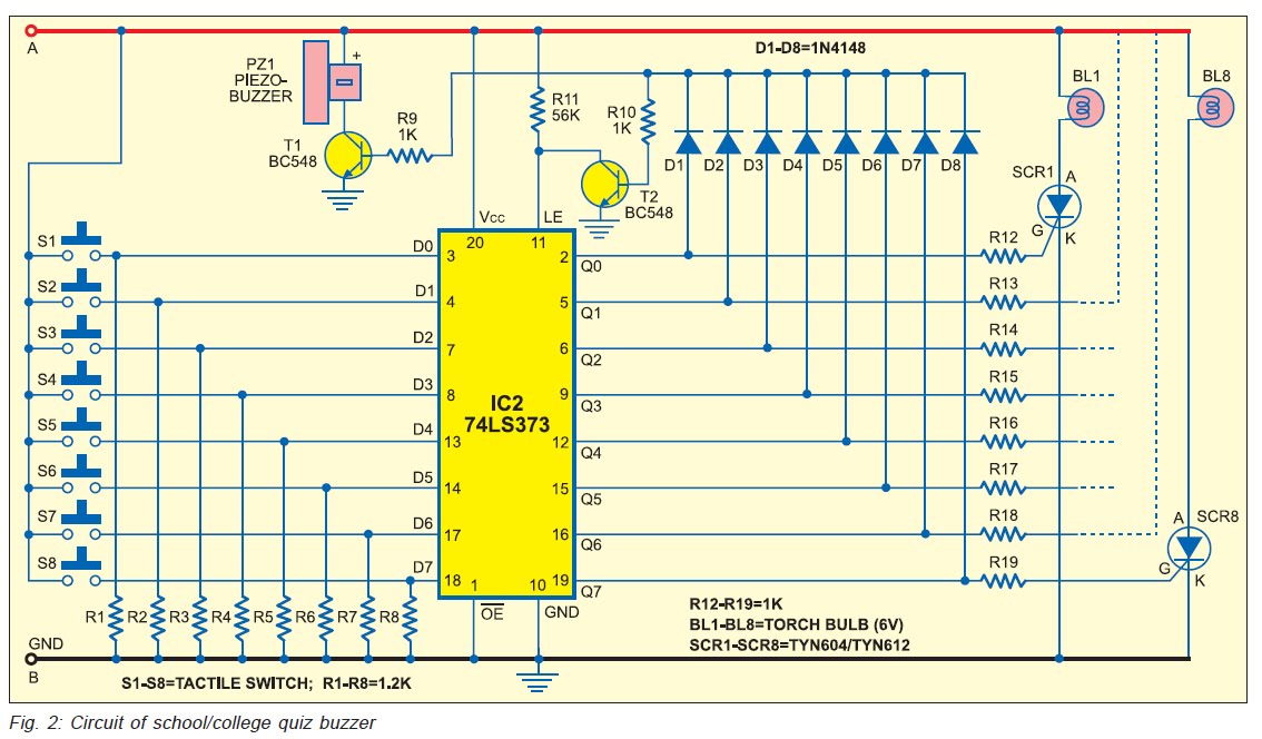
The quiz buzzer circuit given here can be used for up to eight players, which is maximum i n any quiz competition. The circuit uses IC 74LS373 and a few passive components that are readily available in the market. The circuit can be divided into two sections: power supply and quiz buzzer. Fig. 1 shows the power supply section. The regulated 5V power supply for the quiz buzzer section is derived from AC mains. The 230V AC mains is stepped down to 7. 5V AC by transformer X1, rectified by bridge rectifier BR1, filtered by C1 and regulated by regulator IC1. Capacitor C2 bypasses ripples in the regulator output. Fig. 2 shows the quiz buzzer section. At the heart of this section is IC 74LS373, an octal latch that is used to transfer the logic state at data input pins D0 through D7 to the corresponding Q0 through Q7 outputs.
Data pins D0 through D7 are normally pulled low by resistors R1 through R8, respectively. One terminal of push-to-on switches S1 through S8 is connected to +5V, while the other terminal is connected to the respective data input pins. The switches are to be extended to the players through cord wire. The torch bulbs BL1 through BL8 can be housed in boxes with the front side of the boxes covered with a white paper having the name or number of the contestant written over it for easy identification.
Place the boxes above the head level so that these can be seen by the audience also. When the power is switched on using switch S9 (provided terminals A` and B` of both the power supply and quiz buzzer sections are interconnected), the circuit is ready to use. Now all the switches (S1 through S8) are open and Q0 through Q7 outputs of IC 74LS373 are low. As a result, the gates of silicon-controlled rectifiers SCR1 through SCR8 are also low. As soon as a contestant momentarily presses his respective switch, the corresponding output data pin goes high.
This triggers the corresponding SCR and the respective bulb glows. At the same time, the piezobuzzer (PZ1) sounds as transistor T1 conducts. Simultaneously, the base of transistor T2 becomes high to make it conduct. Latch-enable (LE) pin 11 of IC2 is tied to ground to latch all the Q0 through Q7 outputs. This restricts further change in the output state due to any change in the state of switches S1 through S8 by any other contestant. Only one of the eight torch bulbs glows until the circuit is reset by on/off switch S9. Note. The complete kit is available at Kits n` Spares outlet. 🔗 External reference
Related Circuits
Building a competition buzzer set involves the construction of a contest buzzer system. The kit includes an etched, undrilled printed circuit board, a programmed PLD, a 556 timer, various mounting hardware, and a detailed assembly manual. The kit is...
This design utilizes four integrated circuits (ICs) and features four input circuits with four independent outputs, along with a single master reset switch. The outputs are configured with light-emitting diodes (LEDs), which can be modified to control lamps or...
This project is designed for a quiz competition involving up to four contestants or teams. Each contestant is equipped with a trigger push-switch and an LED. When a trigger switch is activated, it illuminates the corresponding LED, activates a...
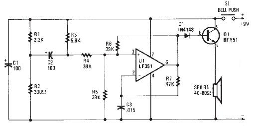
This electronic door buzzer circuit schematic has a straightforward function and is simple to construct. The circuit employs an LF351 operational amplifier along with a few common electronic components. When the S1 push-button is pressed, a positive voltage is...
The drive circuit is a basic drive recently designed to accommodate a 27mm passive piezoelectric buzzer, aiming for a sound output exceeding 100dB while minimizing power consumption. Due to constraints related to product cost and structural size, the circuit...
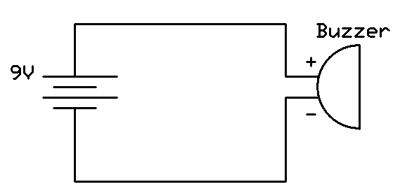
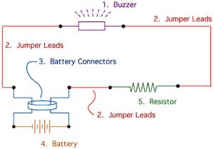
This project involves connecting the positive terminal of the battery to the positive lead of the buzzer and the negative terminal of the battery to the negative lead of the buzzer. Typically, the positive lead of the buzzer is...