
Color-Bar Generator

The circuit comprises several integrated circuits (ICs) that work collaboratively to generate an NTSC video output signal conforming to the RS-170 standard. IC5 is designated as the synchronization generator, producing the necessary timing signals that ensure proper synchronization of the video output. This synchronization is essential for maintaining the integrity of the video signal during transmission.
The color video signals are produced by IC1, IC2, and IC3. Each of these ICs is dedicated to generating one of the primary colors: red, green, and blue (RGB). The output from these ICs is essential for creating a full-color video signal. Specifically, IC3 operates as a 2-counter, which serves to drive the 4-bit counter IC1. This configuration allows for precise control over the timing and sequencing of the color signals.
Gates IC2a and IC2b are critical components in forming the RGB video signals. These gates process the outputs from the respective color ICs to ensure that the signals are properly combined and formatted for encoding. The output from these gates is then fed into the encoder section of IC6.
IC6 plays a pivotal role in the overall circuit by encoding the RGB signals along with the synchronization signals generated by IC5. This encoding process is crucial for converting the individual color signals into a composite NTSC video signal. The final output is made available at test point TP12, where it can be monitored or utilized in further applications.
The design of this circuit emphasizes the importance of each component in the video signal generation process, ensuring that the output adheres to the required standards for NTSC video. Proper functioning of the synchronization, color generation, and encoding stages is vital for achieving high-quality video output. IC5 generates RS-170 NTSC synch. IC1, IC2, and IC3 make up the red, green, and blue video signals that drive the video encoder section of IC6 to make up the color bars. IC3 is an a 2 counter that drives 4-bit counter IC1. Gates IC2a through IC2b form the R, B, and G, video signals. IC6 encodes these, plus synch, to form an NTSC video output signal, which appears at TP12.
Related Circuits
This design outlines a simple 1 kHz square wave generator utilizing a few components and the LM3909 integrated circuit, which is beneficial for testing audio equipment. The circuit operates on a single 1.5V battery cell, producing a maximum output...
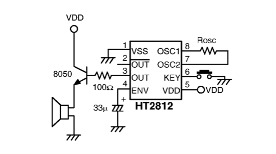
A sound generator is needed for a room monitoring system. Suggestions for an electronic design are requested, as the HT2810 or similar components are not preferred. The sound generator circuit for a room monitoring system can be designed using a...
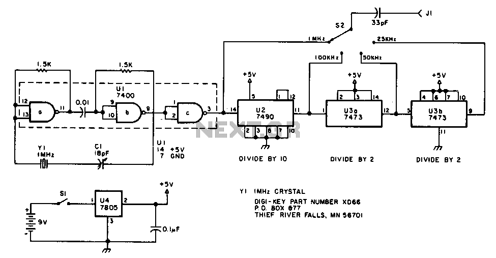
The oscillator section employs three sections of a 7400 quad NAND gate integrated circuit. The 1 MHz signal generated by the oscillator is input into a 7490 decade counter, which is configured to divide by ten, producing a 100...
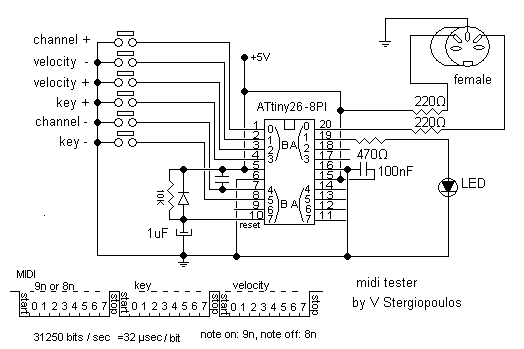
This circuit based on ATtiny26 but it could be anyone microcontroller of AVR family. Produce stable one MIDI tone and you can change it by press some keys like to change midi channel 0-15, velocity 0-127, pitch 0-127. It...
After the recent demise of our multifunction signal generator, we decided to make one of our own. The circuit uses a PIC16F870 (about $3), an R/2R resistor ladder network (for a real fast and cheap D/A), and a few...
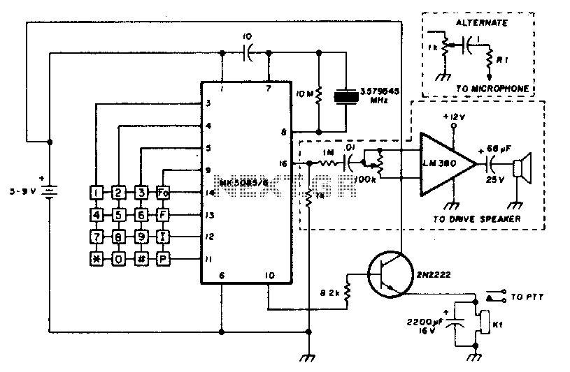
The circuit requires a minimum number of components and utilizes a low-cost standard 379.545 MHz television color-burst crystal. The speaker can be omitted, allowing the output to be directly connected to the microphone input of a transmitter. The circuit design...