
Midi Generator with ATtiny26-8PI
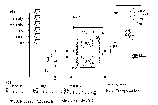
The described circuit employs an ATtiny26 microcontroller, which is part of the AVR family, to generate a stable MIDI tone. The design allows for user interaction through key presses, enabling the modification of MIDI parameters such as channel (0-15), velocity (0-127), and pitch (0-127). The circuit initializes with a central tone of C at MIDI channel 0 and a velocity setting of 30, ensuring a consistent starting point for sound generation.
The MIDI tone generation is achieved through a combination of digital signal processing techniques implemented within the microcontroller. Each tone corresponds to two MIDI events: "note on" and "note off". This dual-event system is essential for creating a realistic musical experience, as it allows for the control of note duration and articulation.
Key presses are detected using a matrix keypad or individual push buttons connected to the microcontroller's input pins. The microcontroller processes these inputs to alter the MIDI parameters accordingly. For instance, pressing a specific key can increment or decrement the MIDI channel, adjust the velocity, or change the pitch of the generated tone.
An LED indicator is incorporated into the design to provide visual feedback to the user. This LED illuminates whenever a command is executed via key presses, signaling the initiation or termination of the MIDI tone. The LED's state is controlled by the microcontroller, which toggles it on during the "note on" event and turns it off during the "note off" event.
To facilitate the MIDI communication, the circuit includes a MIDI output interface that adheres to the standard MIDI protocol. This typically involves a 5-pin DIN connector through which the MIDI messages are transmitted to external devices such as synthesizers or MIDI controllers.
The overall design emphasizes simplicity and functionality, making it suitable for various applications in electronic music production and performance. The use of the ATtiny26 allows for a compact and efficient circuit, while the flexibility in MIDI parameter adjustments enhances the user experience.This circuit based on ATtiny26 but it could be anyone microcontroller of AVR family. Produce stable one MIDI tone and you can change it by press some keys like to change midi channel 0-15 , velocity 0-127, pitch 0-127. It is start from center tone (C) at channel 0 with velocity 30. Every tone is equivalence with two midi events "note on" and "note off". A LED is used to show the start and stop of the midi tone. This LED is turn-on every time a command is executed by the key pressing. 🔗 External reference
Related Circuits
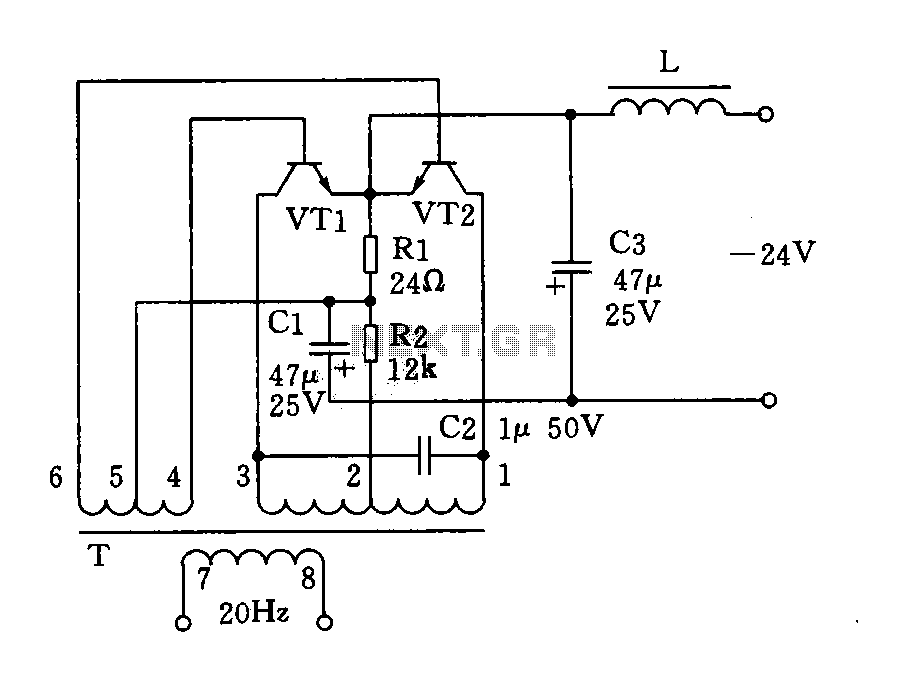
The circuit described is a 20Hz signal generator suitable for telephone ringing systems, alarm systems, and various other electronic applications. It consists of a transformer (T) and two transistors (VT1 and VT2), forming a push-pull oscillator. The two transistors...
After the recent demise of our multifunction signal generator, we decided to make one of our own. The circuit uses a PIC16F870 (about $3), an R/2R resistor ladder network (for a real fast and cheap D/A), and a few...
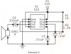
This circuit features an astable oscillator constructed around a 555 timer, generating an alarm tone of 1.8 kHz, which directly drives a speaker. It serves as a fundamental alarm circuit that can be utilized in various projects. Although the...
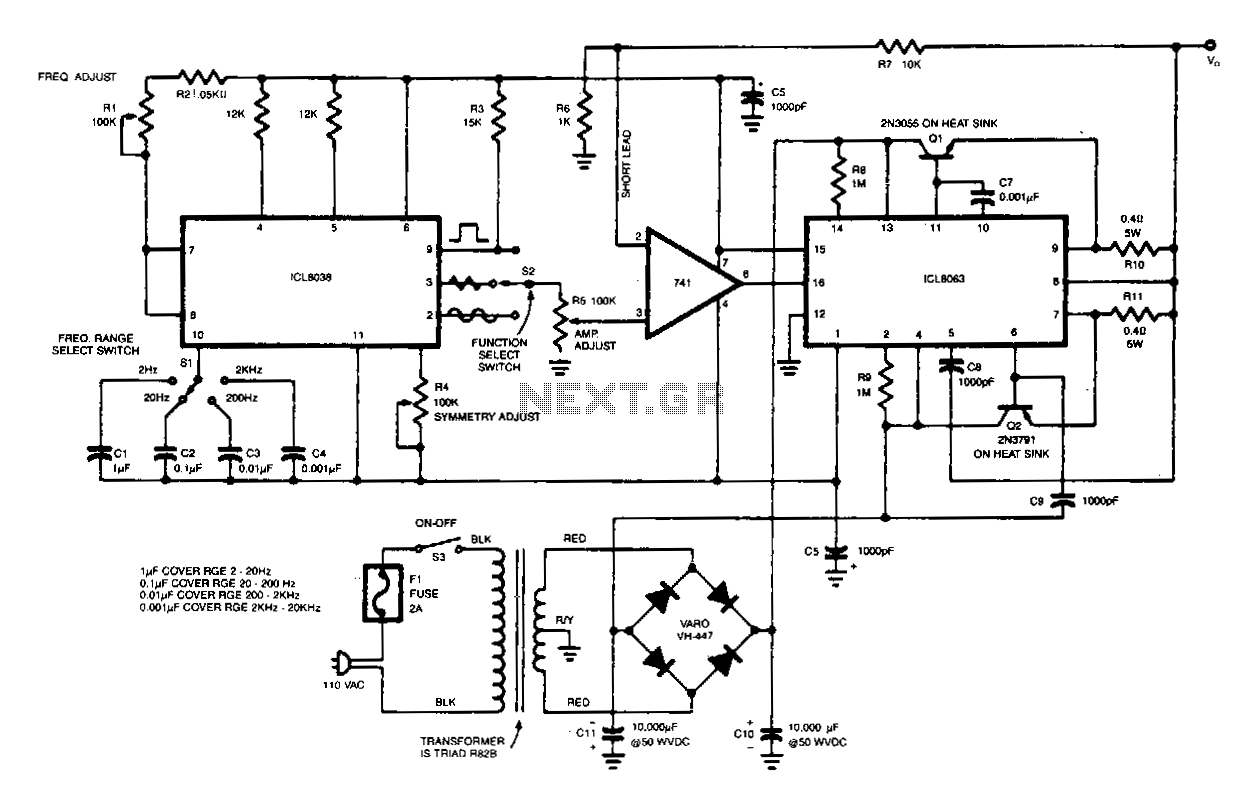
This generator is designed to produce sine, triangular, and square waves within a frequency range of 2 Hz to 20 kHz. It operates as a complete test instrument that can be connected to a standard 110 Vac power supply....
PWM waveforms are widely utilized to regulate the speed of DC motors. The duty cycle of the digital waveform can be established either through an adjustable analog voltage level (as seen in a NE555-based PWM generator) or through digital...
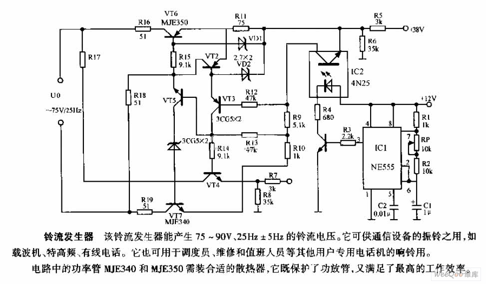
The ring current generator can produce a ringing current voltage of 75-90V and 25Hz ± 5Hz. It is suitable for use in vibrating rings in communication devices, such as carriers, ultrahigh frequency systems, and wire telephones. Additionally, it can...
Warning: include(partials/cookie-banner.php): Failed to open stream: Permission denied in /var/www/html/nextgr/view-circuit.php on line 713
Warning: include(): Failed opening 'partials/cookie-banner.php' for inclusion (include_path='.:/usr/share/php') in /var/www/html/nextgr/view-circuit.php on line 713