
Tone dial generator

The circuit design is based on a minimalistic approach, leveraging the characteristics of the 379.545 MHz television color-burst crystal, which is commonly used for synchronization in video applications. This crystal serves as the primary frequency reference for the oscillator circuit, ensuring stable and accurate signal generation.
The oscillator can be configured using a simple transistor or an operational amplifier in a feedback loop, which will amplify the oscillation generated by the crystal. The output can be configured to provide a clean, square wave signal that can be easily interfaced with other electronic components.
In this configuration, the elimination of the speaker reduces the complexity and size of the overall circuit. Instead of driving an audio output, the circuit's output can be fed directly into the microphone input of a transmitter. This allows for a more streamlined design, particularly useful in applications where audio feedback is not required, and only the signal transmission is necessary.
To ensure optimal performance, it is essential to consider the impedance matching between the output of the oscillator circuit and the microphone input of the transmitter. This may involve the use of passive components such as resistors or capacitors to condition the signal and prevent distortion.
Overall, this circuit design exemplifies an efficient use of components while maintaining functionality, suitable for various applications in RF transmission and signal processing.The circuit requires a minimum of parts and uses a iow cost standard 379545-MHz television color-burst crystal The speaker can be eliminated and the output fed directly into the microphone input of a transmitter.
Related Circuits
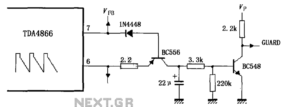
As illustrated in FIG TDA4866, the circuit consists of an external signal generator circuit protection. The internal protection circuit's role is to manage control, while the external protection circuit performs its functions. During normal operation, the vertical amplitude of...
A high voltage power supply DC converter that operates between 3V to 500V has been suggested for use with Geiger tubes. However, during simulation, the output remained at nearly 9V, which matches the input voltage. The schematic drawn has...
The circuit below demonstrates how to construct a DAQ_LITE device, accompanied by an image of the finished PCB board. It is important to note that the 80mA fuse depicted in the image and the nearby protection diode are recommended...

Using an EXAR XR2206, this generator will produce sine, square, and triangular waves from 10 Hz to 100 kHz. The XR2206 chip, R7 controls frequency, and S5 through S8 select the frequency range. U3 produces a TTL-compatible square-wave output,...
There are various methods to create pedal generators, utilizing different components such as bicycle parts or exercise bikes as a foundation. Each approach has its advantages and disadvantages, but for individuals who have not constructed one before and wish...

An MPF102 FET oscillator drives a dual-gate MOSFET buffer. The MPF102 is configured as a Hartley oscillator. If desired, an audio voltage can be coupled to the junction of R4, R5, and C5 with an extra coupling capacitor (~1...