
Color offset printing circuit
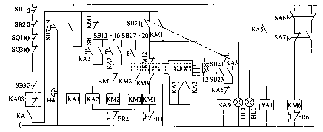
The operation control circuit is designed to ensure efficient and safe management of the main motor M1 and the low-speed motor M2. The use of button switch SB21 initiates the entire control sequence, activating the contactor KM1, which plays a crucial role in the starting and operational phases of the main motor. The self-locking mechanism ensures that once activated, the circuit remains engaged, allowing for a stable operation until intentionally stopped.
The integration of feedback systems, such as the slip clutch speed negative feedback loop control (EA2), allows for precise control over the motor speeds, enhancing the performance and reliability of the machine. The design incorporates multiple safety features, including electrical interlocks, which prevent simultaneous operation of motors M1 and M2, thereby reducing the risk of mechanical failures or accidents during operation.
The local control circuit provides flexibility in operation, allowing for slow movements necessary for maintenance and calibration tasks. The Jog and long vehicle functions enable operators to maneuver the machine easily, ensuring that it can be adjusted for various tasks without compromising safety or efficiency. The careful arrangement of control buttons and relays facilitates intuitive operation, making it easier for users to interact with the system while maintaining a high level of control over the machine's functions.The operation control circuit mainly by the button switch SB21. Contactor KM1 composed contactor KM1 main contact directly control the operation of the main motor Ml. Main motor Ml as the prime mover of the motor slip, the slip clutch can to drag the active machine running. The control principle is that when you press the SB21, contactor KM1 eligible suction power combined self-locking, so that the main motor Ml starting, running lights HLZ light. At the same time, KM normally open contact closure, connected to the slip clutch speed negative feedback loop control system EA2 power, the speed control system, AC contactor KM1 contacts will have the following effects.
1) KM1 normally open, closed, make speeder power. Since KA3 (fixed speed) was released state, so speed control system so that the host is given before the low-speed operation speed. 2) KM1 normally open, closed, turns on a KA3 circuit, constant speed to prepare for the start. 3) KM1 normally open and close the print control circuit power is turned on for the realization of the printing control ready.
4) KM. Normally closed contact off, cut off M2 (low speed motor) control power, implementation and local electrical interlock. When the button is pressed SB21, SB21 mechanical interlock normally closed switch off, cut off the relay KA3 coil circuit can be realized from fixed speed machine is switched to low speed.
(2) local control circuit is slow drag of low-speed electric motor M2. In idle mode operation of the machine, in order to facilitate assembly and calibration of the plate, drum scrubbing, conduct test drum rotation, printing and other printing pressure debug preparations, local control circuit carve Jog and long vehicles in two forms, the slow movement is the point by operating the button SB13 ~ SB16 and SB17-SB20 real reproduced. SB13 ~ SB16 Control JOG, SB17 ~ SB20 control Jog reverse (reverse). Releasing said push button switch, KM2 or KM3 loss of power, M2 stops running. The long slow car, through the operation button switch SB11 to achieve. When you press the SB11 relay KA2 was electric suction combined self-locking, AC contactor KM2 pull power, then M2 operates in 3.5r / min speed, closing the normally open additional KA2 also turned combined pressure control power, low-speed test and check printing ready.
Meanwhile KM2 normally open, closed, turning the electromagnetic clutch YA1 coil circuit, M2 and the main motor shaft connected. KM1, KIVt2, KM3 normally closed contacts are electrically interlocked play role in ensuring low-speed electric motor M2 and the main motor Ml can not operate simultaneously.
Related Circuits
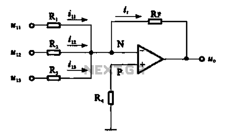
An adder circuit, specifically the inverting adder circuit, utilizes the inverting input of an operational amplifier to process signals. Voltage inputs are added through resistors connected to the inverting input terminal of the operational amplifier. The circuit configuration, as...
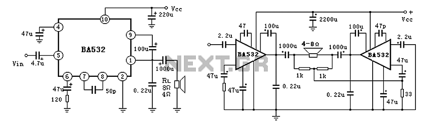
BA532 is a low-frequency power amplifier circuit designed for an output transformerless (OTL) application, capable of delivering up to 5.8W of output power. It features built-in protection against load short-circuits, over-voltage, and over-temperature conditions. The amplifier is housed in...
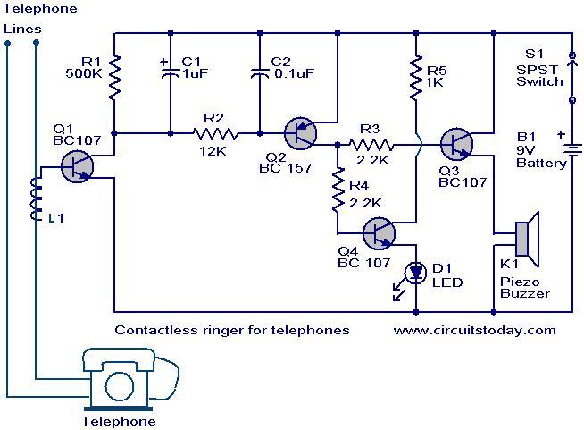
The contactless telephone ringer circuit is designed to produce an audible ring and a visual indication when a call is received. Its primary advantage lies in the absence of direct contact between the telephone line and the circuit, which...
The VU meter is categorized into two types: those that use needle instruments and those that employ LED columns. A VU meter sound level meter is essential for both tube amplifiers and integrated amplifiers. Currently, there are numerous integrated...
VCR Camera Video Detector Switch Controller Circuit. This video detector switch controller circuit utilizes the video output from a VCR or camera to... This circuit functions as a video detector switch controller, designed to manage the video output from a...
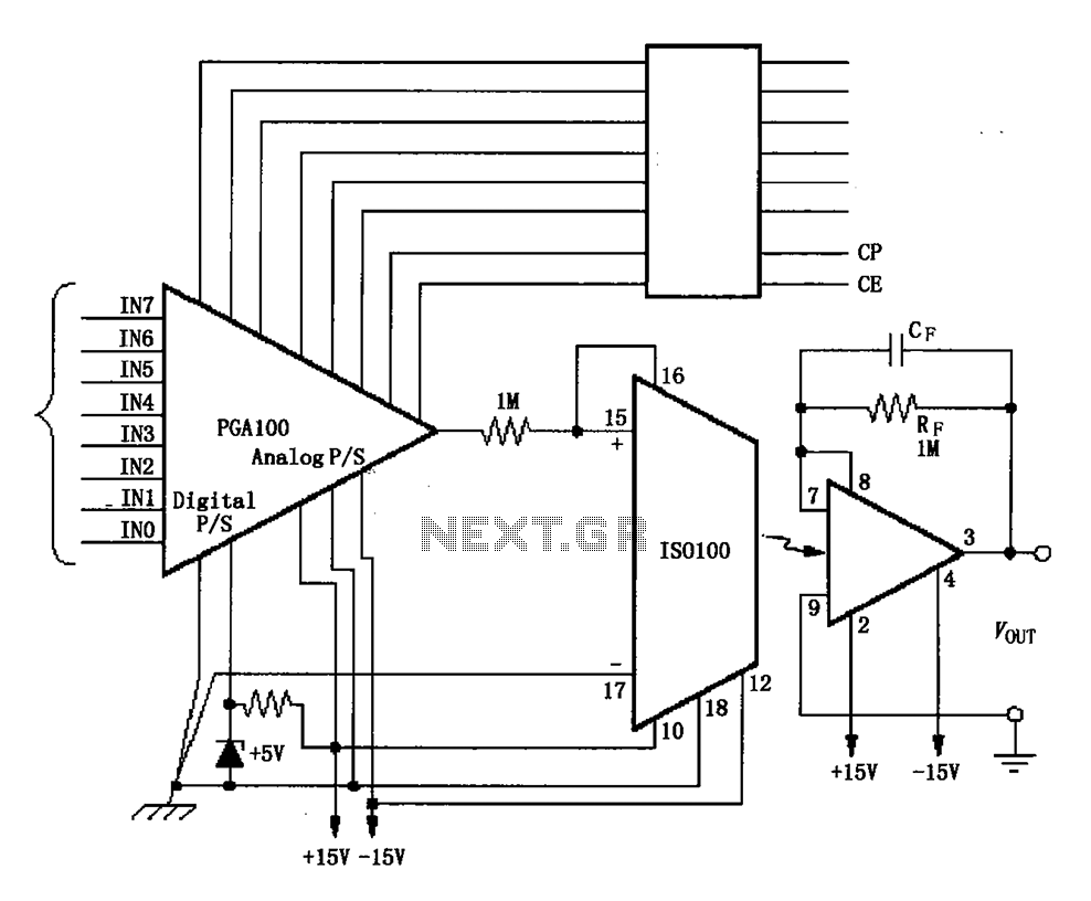
The ISO100 multichannel data acquisition system comprises a programmable gain amplifier isolated by an optocoupler, a programmable amplifier (PGA100), and an isolation amplifier (ISO100). The optocoupler selects three channels and is coupled to the programmable gain amplifier, which can...
Warning: include(partials/cookie-banner.php): Failed to open stream: Permission denied in /var/www/html/nextgr/view-circuit.php on line 713
Warning: include(): Failed opening 'partials/cookie-banner.php' for inclusion (include_path='.:/usr/share/php') in /var/www/html/nextgr/view-circuit.php on line 713