
VCR Video Detector Switch Controller Circuit
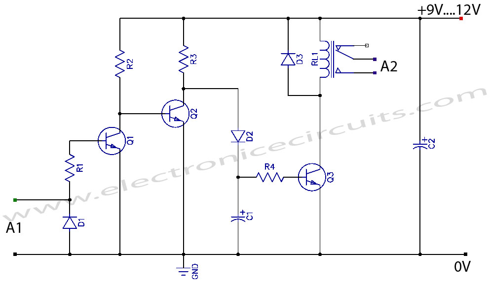
This circuit functions as a video detector switch controller, designed to manage the video output from a VCR (Video Cassette Recorder) or a camera. The primary objective of this circuit is to detect the presence of a video signal and switch the output accordingly. It is particularly useful in applications where automated switching between multiple video sources is required.
The core components of the circuit typically include a video signal input, a detection circuit, and a switching mechanism. The video signal input receives the output from the VCR or camera, which is then processed by the detection circuit. This detection circuit usually employs a comparator or an operational amplifier configured to monitor the amplitude of the incoming video signal. When a valid video signal is detected, the circuit triggers the switching mechanism.
The switching mechanism can be implemented using either a relay or a solid-state switch, depending on the desired application and load requirements. A relay provides physical isolation and can handle higher power levels, while a solid-state switch offers faster switching times and increased reliability due to the absence of moving parts.
Additional features may include indicators such as LEDs to show the status of the detected video signal and the active output. The circuit may also incorporate a delay timer to prevent false triggering from transient signals or noise. Proper power supply decoupling and filtering are essential to ensure stable operation, particularly in environments with electrical noise.
Overall, this video detector switch controller circuit offers a practical solution for managing video inputs in various electronic applications, enhancing automation and user convenience.VCR Camera Video Detector Switch Controller Circuit This video detector switch controller circuit uses the video output from a VCR or camera to.. 🔗 External reference
Related Circuits
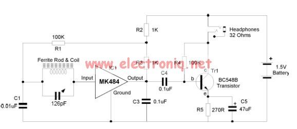
The MK484 AM radio circuit offers a comprehensive solution featuring an RF amplifier, detection, and an automatic gain control (AGC) circuit. It requires only a few external components to achieve high-quality AM tuning. The circuit has an input impedance...
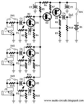
The following circuit illustrates a Mini Audio Mixer with Level Control Circuits. Features include switchable high/low sensitivity, providing high performance. The Mini Audio Mixer circuit is designed to facilitate the mixing of multiple audio signals while allowing for level control...
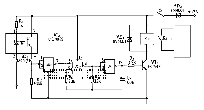
An anti-theft car audio system circuit is depicted, powered by a 12V DC supply from the car battery. Upon closing switch S1, the light-emitting diode in optocoupler IC1 activates, causing the phototransistor to conduct. This results in a high-level...
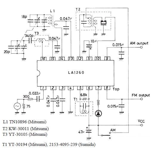
This FM IF MW radio receiver circuit schematic utilizes the LA1260 integrated circuit (IC), which is suitable for AM and FM radio receiver electronic projects. The LA1260 incorporates numerous functions and features essential for radio receiver applications, including a...
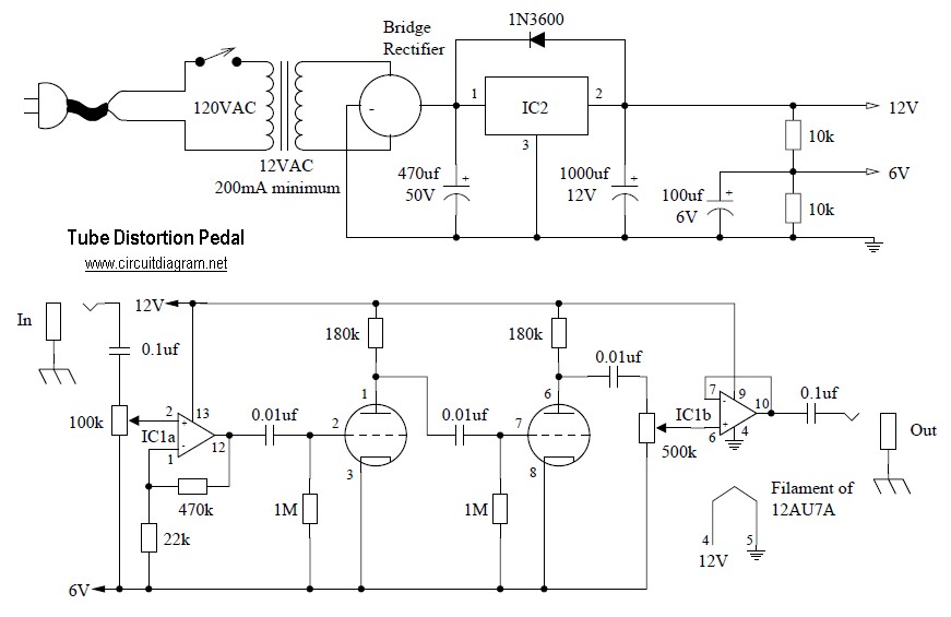
Tube distortion pedal circuit diagram. IC1: 747 dual op-amp; other ICs may be substituted, but the pinout will differ, so the datasheet should be checked. IC2: LM340K-12V voltage regulator. All resistors are 1/2 W. The bridge rectifier is a...
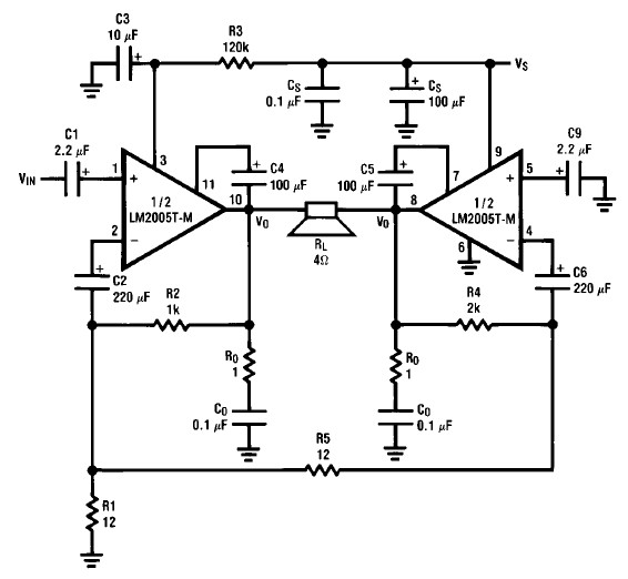
A simple 20-watt amplifier electronic project can be designed using the LM2005 dual high-power amplifier, which is engineered to provide optimal performance and reliability for automotive applications. The LM2005 20-watt amplifier has a high current capability of 3.5A, allowing...