
With a CD4011 CD4518 making colorful cycle decorative lights

The circuit is designed to provide a visually appealing light display through the use of a microcontroller and other electronic components. The power conversion section is critical, as it transforms high-voltage AC into a stable low-voltage DC that powers the control circuit. The rectification process using diodes ensures that the AC input is converted efficiently, while the filtering and regulation components maintain a consistent voltage level necessary for reliable operation.
The clock signal generator is an essential aspect of the circuit, enabling precise timing control for the lighting sequence. The multi-resonant oscillator formed by the NAND gate and passive components creates a square wave output that serves as the timing reference for the entire system. The RS flip-flop configuration ensures that the output states are stable and only change in response to the clock pulses, allowing for predictable and repeatable light patterns.
The use of CMOS technology in the A2 integrated circuit provides low power consumption and high-speed operation, making it suitable for applications involving complex light control. The three-state outputs (Q1, Q2, Q3) allow for various combinations of light activation, facilitating the creation of different colors through additive mixing. This method of color generation is fundamental in applications such as decorative lighting, where visual effects are paramount.
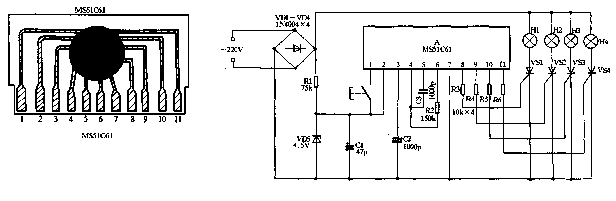
Furthermore, the design incorporates safety features, such as voltage limiting and isolation, to protect the control circuitry from potential over-voltage conditions. The thyristors used for lamp control are chosen for their ability to handle high currents, ensuring reliable operation of the decorative lights. Overall, this circuit exemplifies an effective approach to creating dynamic lighting effects using electronic control systems. Colorful decorative lights loop circuit shown in Figure 3-22. It consists of the power conversion circuit, a clock signal generator toner color and lighting control circuit of several components. 220V AC after VD1 ~ VD4 bridge rectifier, on the one hand lantern loop for power; on the other hand by Rl buck limit, VD6 regulator, VD5 cl filtering and isolation for the control circuit to provide a stable DC voltage of about lov. Al and peripheral components of a clock signal generator, wherein the NAND gate I, and RP, R3 and C2 form multi-resonant oscillator, NAND gate I, t constitute RS flip-flop, pulse oscillator for shaping then the NAND gate delivery to the clock pulse input CP of A2.
A2 is a CMOS digital integrated circuits with dual synchronous addition counting function, the positive pulse and the NAND gate t sent in its internal binary coding, and Ql, Q2, Q3 output of the three state circulation changes occur in combination, make along with the corresponding lights on, off. According to the principle of the three primary colors of light, it will be able to produce seven kinds of color of external light, specifically as shown in Table 3-1.
For example, when a first clock pulse, Ql end A2 output high, single red light to the thyristor VS1 conduction, lantern Hl; when the second pulse arrives, Q2 ended output high-A2 level, VS2 subsequently turned, H2 glows green; when the third clock pulse, Ql A2, Q2 of simultaneously output high. vsl, VS2 are conduction, Hl, H2 lit simultaneously, according to the principles of color mixing, external light turns yellow when {.
eighth clock pulse rushed to come, QI A2 of ~ Q3 output low level, H1 ~ H3 put out the whole moment; while Q4 terminal A2 output high power level, the signal is directly sent eight clear terminal R, so A2 internal circuit is reset; when the first nine clock pulses into A2, cycle the process.
Related Circuits
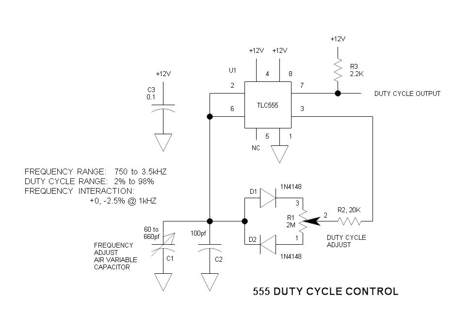
This is a simple oscillator circuit that varies the duty cycle over a wide range without affecting the frequency. It is a variation of the simple 555 astable multivibrator. The oscillator circuit utilizes the 555 timer IC configured in astable...
The circuit utilizes a 220V AC input, which is converted to DC using a VD1-VD4 bridge rectifier. This rectified voltage is used to power four lights (H1 to H4). The circuit also includes a resistor (R1) for voltage limiting...
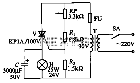
The circuit employs thyristor control. The flash frequency is determined by resistors Ri, RP, Rz, and capacitor C. By adjusting the electrical locator RP, the flash frequency can be varied from 0.5 Hz to several Hz. The described circuit utilizes...
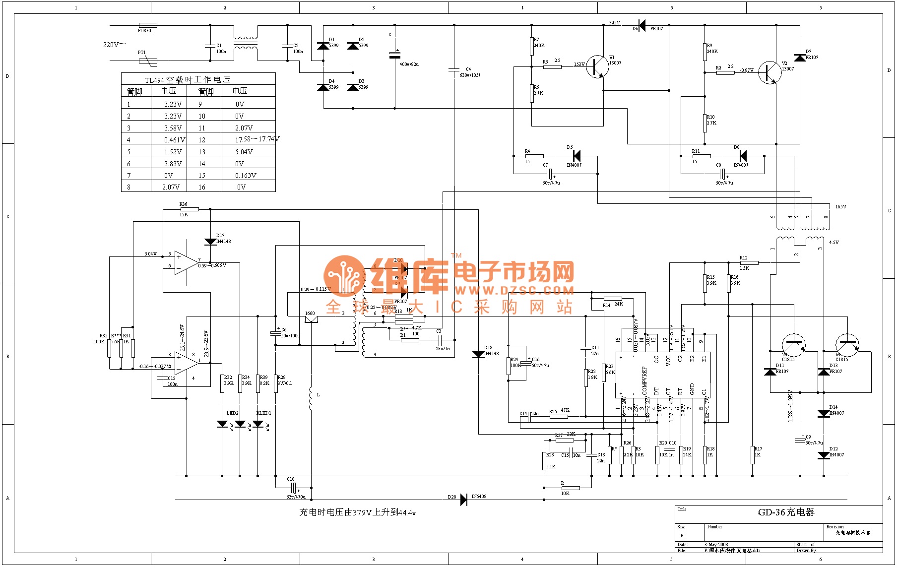
The TL494 is a voltage-driven pulse width modulator produced by the United States company IR. It serves as a switching power circuit in various applications, including displays, computers, and other system circuits. The output transistor of the TL494 can...
An isolation transformer is a transformer used to transfer electrical power from a source of alternating current (AC) to equipment while isolating the powered device from the power source. An isolation transformer serves several critical functions in electrical systems. Primarily,...
The circuit below turns on a light corresponding to the first of several buttons pressed in a "Who's First" game. Three stages are shown but the circuit can be extended to include any number of buttons and lamps. Three...