
Color Sensor from a Reversed LED and Op Amp
Put the LEDagainst a light source, such as a desk lamp. See the voltage Now, hide the LED in a dark place. See a decrease in voltage Photodiodes are used in robots and devices as light sensors. Photodiodes have a spectrum wavelength to which they are most sensitive, usually infrared. But, not surprisingly, a reversed LED is most sensitive to the same color of visible light as it normally emits. For example, if a circuit uses a reversed green LED, the most current will flow from exposure to green light.
Unfortunately, even under the best conditions, photodiodes (and reversed LEDs) don`t provide a lot of current flow. The output of the photodiode needs to be amplified for the light-detection signal to be useful in most circuits.
A photodiode amplified by a built-in transistor is called a phototransistor. You can connect a standalone photodiode to the input of a standalone transistor. But, it isn`t easy to control the gain of a single-transistor amplifier, and there are issues with signal noise and the amount of input current required. Instead, a better method for amplifying low-power signals in a high-quality repeatable way is an op amp chip (operational amplifier).
Putting this all together - a color sensor can be made from a reversed LED and an op amp chip. In fact, TAOS did just that with their TSLR257 (red), TSLG257 (green), and TSLB257 (blue) sensors. LED1: Normally an LED has the diode arrow pointed down toward ground because conventional current flows that way. But, this reversed LED points up. The more light that hits it, the more current will flow. IC1: The op amp takes the weak signal of the reversed LED, amplifies it, and sends it out the output pin.
IC1 must be a ultra-low input current op amp. That means the chip can work with very little input current, which is good because the reversed LED can only produce a little current. This trick won`t work with an old-fashioned op amp, because it requires a lot more input current. Resistor R1 allows a teeny tiny bit of the op amp output to feed back into the input signal. If R1 didn`t exist, the high-gain op amp would amplify the LED1 signal so much that it would simply max out at 5V all the time.
But, by taking a bit of current and feeding it back, R1 reduces the LED signal just enough so that the op amp output voltage is a usable level somewhere between 0V and 5V. Think of R1 as the volume control. Crank the resistance too high and the output becomes too loud (oversaturated). Set the resistance too low and the output becomes too quiet to be useful. C1: Because this circuit deals with extremes (low input signal, high resistance, high gain), it may oscillate (change values back and forth) unintentionally.
Therefore, a small amount of capacitance (likely in the picofarad range) can stabilize the signal. However, this same type of circuit appears in white papers and technical notes for both National Semiconductor`s and Texas Instrument`s op amps. So, you can build a color sensor circuit using their parts. Although the circuit will be a lot larger than one integrated into a single component, you`ll be able to select specific wavelength sensitivity through your choice of LED color.
And, you`ll be able to determine the desired amount of signal gain through your choice of feedback resistance. On the next page you`ll see the complete schematic and solderless breadboard for the reversed LED color sensor.
The remainder of the article is devoted to a series of oscilloscope traces showing the photodiode signal in action. These trace tell the story of why certain parts in the circuit improve t 🔗 External reference
Related Circuits
RF Signal Strength Meter circuits are popular RF measurement devices. This circuit is one of the simplest but very useful circuits that satisfies your desired accuracy. The heart of measurement is high accuracy but easy to use Logarithmic Detector...
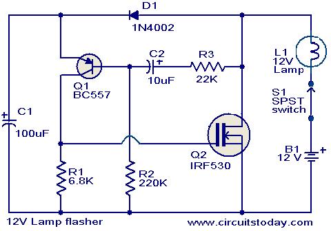
This circuit is a straightforward yet effective solution for flashing 12V lamps, particularly those utilized in automobiles. The flashing mechanism relies on transistor Q1 (BC557) and MOSFET Q2 (IRF530), with Q2 delivering the required drive for the lamp. The...
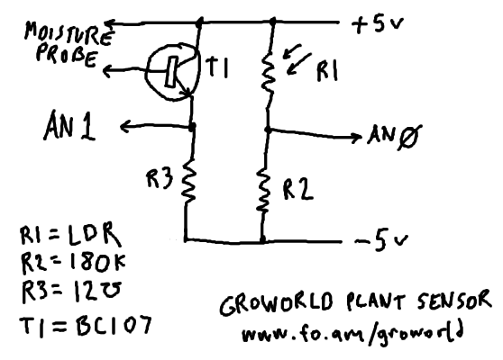
The plan is to implement plant sensing technology for a Groworld installation at Camp Pixelache. The circuitry has been enhanced for durability through soldering. The circuit diagram's component values are influenced by available surplus and donated stock but are...
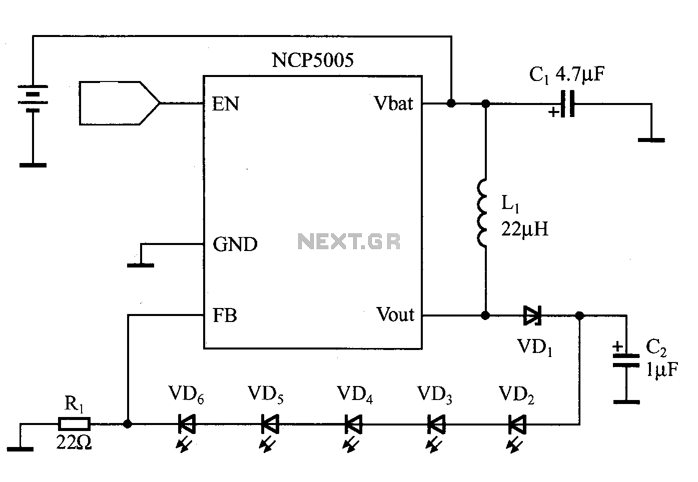
White LEDs can be connected in series or parallel, each method having its own advantages and disadvantages. A key disadvantage of the parallel connection is that the current and brightness of the LEDs do not automatically match. In contrast,...
This regulated power supply can be adjusted from 3 to 25 volts and is current limited to 2 amps as shown, but may be increased to 3 amps or more by selecting a smaller current sense resistor (0.3 ohm)....

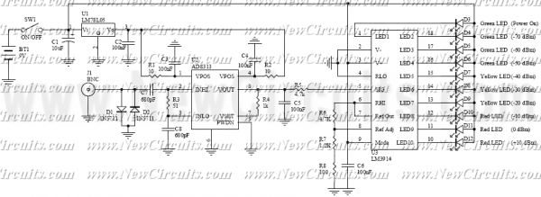
A biaxial magnetic field sensor application circuit is illustrated in the figure. This circuit utilizes a biaxial magnetic sensor HMC1002 along with two AMP04 operational amplifiers (A1, A2) to measure the magnetic field in both the X-axis and Y-axis...
Warning: include(partials/cookie-banner.php): Failed to open stream: Permission denied in /var/www/html/nextgr/view-circuit.php on line 713
Warning: include(): Failed opening 'partials/cookie-banner.php' for inclusion (include_path='.:/usr/share/php') in /var/www/html/nextgr/view-circuit.php on line 713