
Changes inductive boost LED Driver

In electronic circuit design, the choice between series and parallel configurations for white LEDs is critical, as it influences not only the electrical characteristics but also the overall efficiency and reliability of the system. The series connection is often preferred when uniform brightness is essential, as it ensures that the same current flows through each LED, thus maintaining consistent performance. However, the requirement for a higher supply voltage can complicate designs, especially in battery-operated devices where space and weight are at a premium.
The use of a boost converter in the circuit design is a common solution to overcome the voltage limitations posed by battery supplies. This converter steps up the input voltage to a level sufficient to drive the desired number of LEDs in series. The design of the boost converter typically involves an inductor, a diode, a switch (often a transistor), and a capacitor. The inductor stores energy when the switch is closed and releases it to the output when the switch is opened, allowing for a higher voltage to be delivered to the LEDs.
Furthermore, careful consideration must be given to the thermal management of the LEDs and the boost converter, as excessive heat can lead to reduced efficiency and potential failure of components. Heat sinks or thermal pads may be necessary to dissipate heat effectively, ensuring the longevity of the LEDs and maintaining performance.
In summary, the design of LED circuits, whether in series or parallel, requires a thorough understanding of electrical characteristics, power supply limitations, and thermal management to create efficient and reliable lighting solutions.White LED can be used in series or parallel connection, both solutions have advantages and disadvantages. The disadvantage is that parallel the LED current and brightness do not automatically match. Series to maintain the inherent characteristics of the match, but requires a higher supply voltage. Because the white LED forward voltage drop of 3 ~ 4V (typ), either in parallel or in series, the battery voltage is most portable electronic devices are insufficient to drive the LED, so the need for a separate power supply. In a series configuration, the number of LED's that drive the highest voltage limit. If the maximum voltage of 40V, in a series configuration according to the white LED forward voltage, the maximum voltage that can drive up to 13 white LED, the drive current in the range of 10 ~ 350mA continuous state.
Advantage of this configuration is a series of white LED can be used single-wire current; the disadvantage is that when the PCB space is limited (especially when high power), the current density on the copper wire is a problem, but if one in-line mode white LED fails, all white LED will be turned off. However, from a design point of view, if there is a knife only white LED, the battery voltage is necessary to enhance the n Vp, it must step-up structure.
You can use inductance element accurately monitor current slope, limiting the EMI uncontrolled instantaneous current. A typical boost topology shown in Fig.
Related Circuits
This simple LED flasher circuit will alternately turn ON and OFF two LEDs. The first LED will illuminate when the second LED is OFF for a certain duration, and then the process will repeat. The LED flasher circuit operates using...
A fluorescent tube is connected in an LC resonant circuit consisting of inductor L2 and capacitor C9. The bidirectional breakdown diode VD4 initiates the starting circuit. When AC power is applied, the gate potential of transistor VT2 increases due...
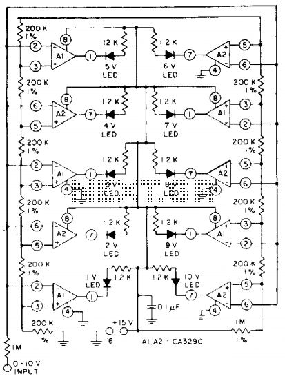
The circuit utilizes CA3290 BiMOS dual voltage comparators. The non-inverting inputs of A1 and A2 are connected to a voltage divider reference. The input signal is applied to the inverting inputs. LEDs are activated when the input voltage reaches...
This LED thermometer is designed for home use, capable of reading temperatures between approximately 60 and 78 degrees Fahrenheit. It utilizes a precision temperature sensor IC, the LM34DZ, which requires no calibration and can measure temperatures ranging from -50°F...
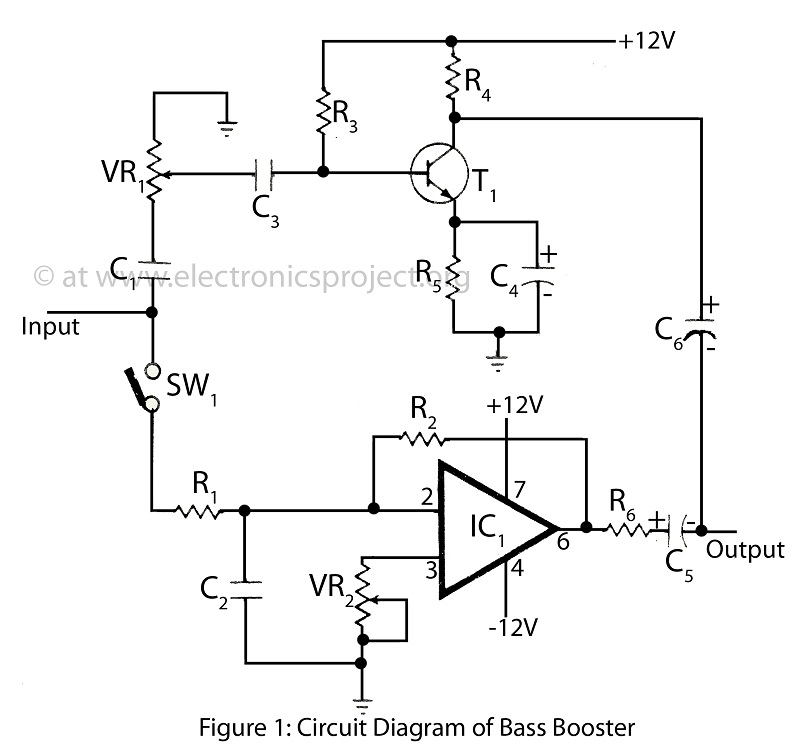
The bass booster featured on this website enhances the beat frequency while maintaining the integrity of the high-frequency response. The circuit diagram for the bass booster, along with various radio circuits, is also provided. The bass booster circuit operates by...
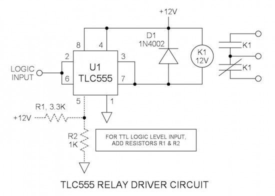
Many integrated circuits possess undocumented features or capabilities. One such example is the TLC555, which can sink a 100mA load down to 1.28V at its output (pin 3). The open-drain transistor reset (pin 7) can also sink 100mA to...