
Colour (Sound) Organ
 Organ")
The colour organ circuit described operates by detecting audio signals through a built-in microphone, which allows it to function independently of any external audio sources. The microphone converts sound waves into electrical signals, which are then processed to control the lighting effects. The circuit can be designed using operational amplifiers to amplify the microphone signal before it is fed into a series of filters that separate the audio frequencies into different bands.
Resistors R10, R11, and R12 play a crucial role in determining the sensitivity and response characteristics of the circuit. By adjusting these resistors, the user can modify how the circuit responds to various audio frequencies, effectively controlling which lights are activated based on the sound input. This allows for a customizable experience, as different musical genres may require different light responses.
The circuit is capable of driving up to 300 watts per channel, indicating that it can control a substantial number of lights or high-power lighting fixtures. This makes it suitable for use in larger venues such as nightclubs or concert halls. However, it is important to note that the circuit is not isolated from the 115 Volt AC line. Therefore, precautions must be taken when handling the circuit, especially if it is exposed or not housed within a protective case. This lack of isolation poses a significant risk of electric shock, and proper safety measures should be implemented to mitigate this hazard.
In summary, the colour organ circuit described is a versatile and powerful device that enhances visual experiences during musical performances. Its ability to respond to sound through a built-in microphone, along with adjustable sensitivity settings, makes it a valuable tool for creating dynamic light displays in sync with audio inputs.Anyone who has been to a night club, concert or school dance has probobly seen a colour organ. Colour organs cause lights to blink and flash to music from your TV, stereo, guitar and even your own voice. The colour organ presented here needs no connection to the sound source, it picks up sound from its built in microphone.
# R10, R11 and R12 control the response of the different lights. # The circuit can handle up to 300 watts per channel. # This circuit is NOT isolated from the 115 Volt line. If it is used with the case opened or not installed in a case, you could re 🔗 External reference
Related Circuits
The basic idea of the project is to make different colored bulbs light at different frequencies of music. The circuit connects to the speaker outputs of your stereo or to the back of your speaker. The music passes through...
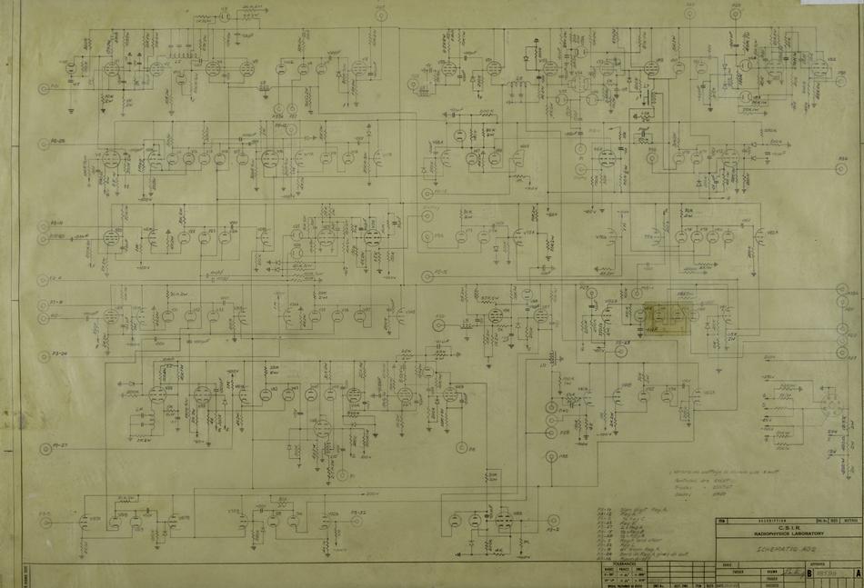
A schematic diagram illustrates the detailed connections between all components in a circuit. These diagrams are utilized for circuit construction and subsequent testing. In the case of CSIRAC, the primary components included vacuum tubes (valves), capacitors, and resistors. Schematic diagrams...
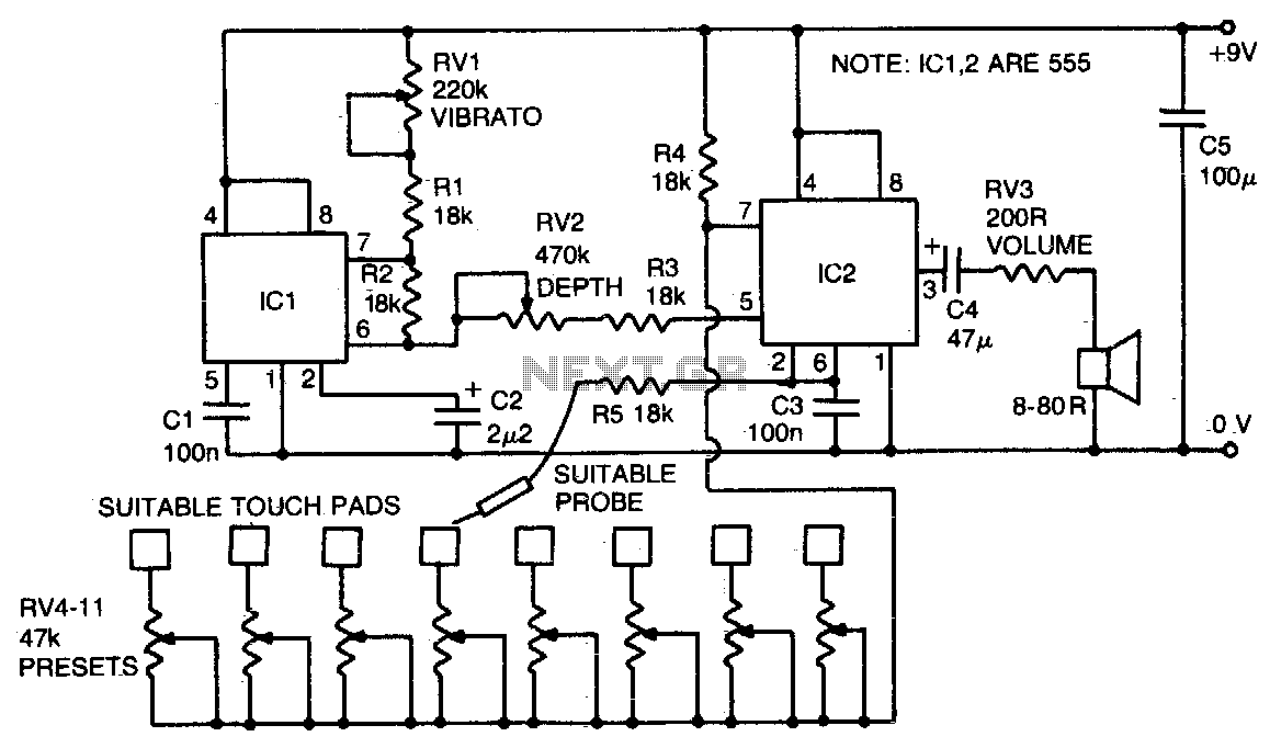
IC2 is an audio frequency oscillator. Its frequency is primarily controlled by the resistance between pins 2 and 7. RV4-11 controls the oscillator frequency, and by touching a stylus (connected via limiting resistor R5 to pin 2) to each...
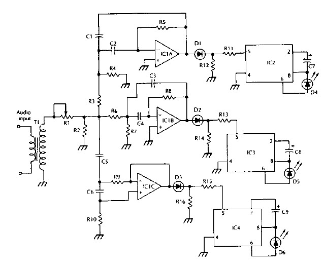
The LM 3909 LED flasher integrated circuit (IC) can be utilized to design various electronic projects. A circuit diagram illustrates the creation of a simple color organ using the LM3909 LED flasher IC. Three active filters process the audio...
This light organ is on the speaker output of the amplifier. The lamps lit on the rhythm of the music. The input signal is amplified by a transformer. Then it goes through a monolingual filters comprising resistors and capacitors...
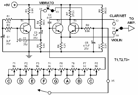
This electronic organ is simple to construct and can provide hours of enjoyment, particularly for children. The circuit is fundamentally an emitter-coupled oscillator consisting of transistors T2 and T3. A square wave voltage can be sampled from the collector...