
combination lock in electronic
This electronic combination lock circuit utilizes the LS7220 IC, which is designed for keypad applications. The circuit operates by interpreting the input from the keypad switches (S1, S2, S3, and S4) connected to the designated pins of the IC. Each switch corresponds to a digit in the combination, enabling the user to input a sequence of four digits.
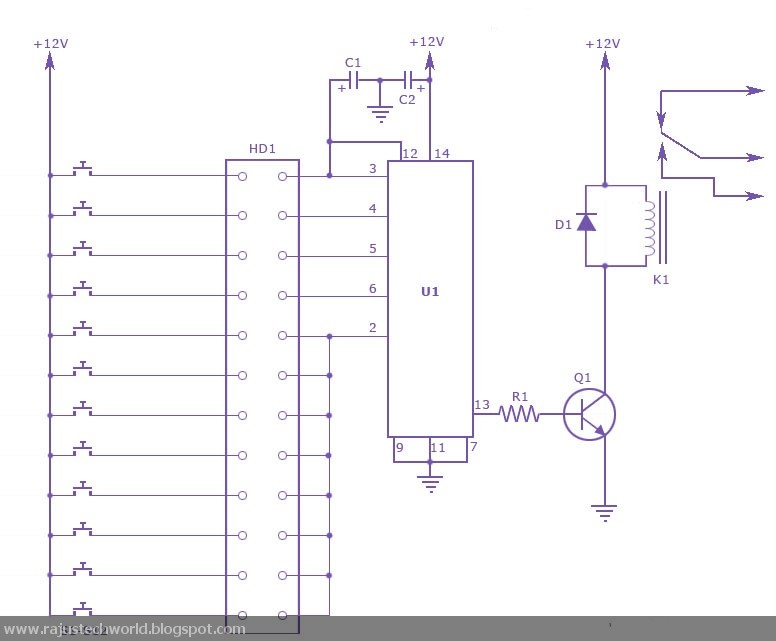
The power supply for the circuit can be adjusted between 5V and 12V, providing flexibility in various applications. It is essential to ensure that the power supply is stable to avoid any malfunction during operation. The LS7220 IC processes the input signals and checks them against the stored combination. If the user inputs the correct sequence, the output pin of the IC activates a relay, allowing it to control external devices such as electronic locks, alarms, or other appliances.
The reset function is crucial for maintaining security. If an incorrect key is pressed, the circuit will reset, requiring the user to start over with the combination entry. This feature is implemented by connecting an additional reset mechanism to pin 2 of the IC.
The timing of the relay activation is controlled by capacitor C1. The selected capacitance value directly influences how long the relay remains activated after the correct combination is entered. A typical value of 6 seconds is suggested for C1, but this can be adjusted based on the specific application needs. Increasing the capacitance will prolong the activation time, allowing the user sufficient time to operate the connected device.
In summary, this circuit provides a straightforward yet effective solution for implementing a four-digit combination lock system, suitable for various electronic control applications. Proper design considerations, including voltage supply, component selection, and timing adjustments, will enhance the reliability and functionality of the lock system.This is the circuit diagram of a combination lock electronic simple using CI LS7220. This circuit can be used to activate a relay to control (the & off) press any device when a preset combination of 4 digits. The circuit can be operated from 5V to 12V. Specify connection combination the appropriate parameters to pin 3, 4, 5 and 6 IC through the head . As an example, if S1 is connected to pin 3 to pin 4, S2, S3, S4 to pin 5 to pin 6 IC, will the combination be 1234. This way we can create all the 4 digit combinations. Then connect the rest of the parameters to the leg 2 of the IC. This will cause IC reset If an invalid key is pressed, and the whole key code has to be entered. When the right key is pressed, the out put (relay) for a period of time is determined be enabled by the capacitor C1.
Here, it should be 6s. Temporary increase increase C1. 🔗 External reference
Related Circuits
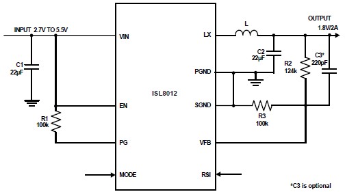
The ISL8012 is a high-efficiency, monolithic, synchronous step-down DC-DC converter that can be designed into a simple electronic project. It supports a maximum continuous output current of up to 2A from an input supply range of 2.7V to 5.5V....
This circuit is designed to protect a power supply or battery. The electric current will be interrupted by a relay when a short circuit occurs. Relays must be selected with a voltage rating equal to the input voltage. It...

This smoke detector electronic project is designed using the LM1801 and common electronic components. The smoke detector circuit diagram does not utilize ionization detection, gas sensors, or optocouplers; instead, it employs two photoresistors (LDRs) and an LED. The circuit...
Voltage is applied to the chip via pins 14 and 7 so that when power is applied to the project, the high and low frequency oscillators will come into operation to produce a wailing sound from the piezo. The...
While many power supplies can be set to limit their output current to a defined level to protect the circuit they are powering, no such protection is available. To enhance the safety and reliability of electronic circuits, it is crucial...
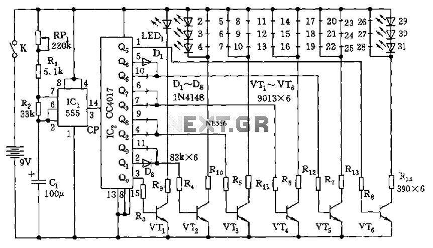
The circuit features a clock pulse generator and a pulse distribution circuit that drives the display circuit. It consists of a 555 timer and resistors RP1, R1, R2, along with capacitor C1, forming an astable multivibrator. The oscillation frequency...