
Electronic Fuse Employs A Relay
To enhance the safety and reliability of electronic circuits, it is crucial to implement current limiting features in power supplies. Current limiting serves as a protective mechanism that prevents excessive current flow, which can lead to circuit damage, overheating, or even catastrophic failure.
Power supplies that incorporate current limiting typically employ various methods to monitor and control the output current. One common approach is to use a feedback loop that continuously measures the output current. If the current exceeds a predetermined threshold, the power supply reduces its output voltage, thereby limiting the current to a safe level.
Additionally, current limiting can be achieved through the use of resistors in series with the load, which can be configured to drop voltage when the current exceeds a specified limit. This method is often simple and cost-effective but may introduce power losses and heat dissipation.
Another advanced method involves the use of electronic components such as transistors or operational amplifiers to create a more sophisticated current limiting circuit. These components can be configured to react quickly to changes in current, providing a more dynamic response to overload conditions.
Incorporating current limiting features into power supplies not only protects the connected devices but also enhances the overall reliability of the power supply itself, ensuring longer operational life and reduced maintenance needs.While many power supplies can be set to limit their output current to a defined level, to protect the circuit they are powering, no such protection is ava.. 🔗 External reference
Related Circuits
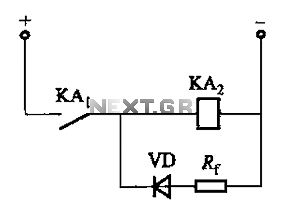
The circuit depicted in Figure 6-24 includes a relay coil with both ends connected in parallel to a resistor (Rf) or an auxiliary diode (VD). This configuration is intended to enhance power after a short circuit occurs in the...
A dual benefit for battery-powered portable devices is provided by Class D audio amplifiers. They produce much less power dissipation than their linear counterparts. Class D audio amplifiers, also known as switching amplifiers, are designed to achieve high efficiency and...
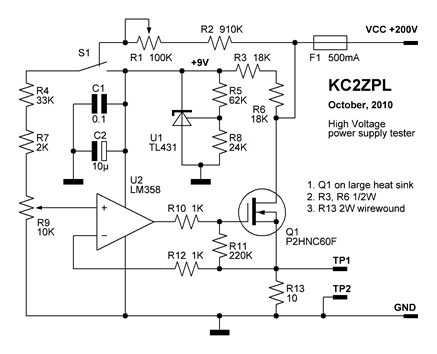
Now that these power supplies are available, it would be beneficial to evaluate their performance. Traditionally, an adjustable load (a robust resistor) is connected to the output to measure both output voltage and current at various points. This allows...

The schematic below illustrates four methods of controlling a relay with a digital logic signal. Figure A can be used in most cases where the relay coil requires 100 mA or less and the input current is 2 milliamps...
A relay (RL1) is activated with a 100-second delay when a +12V power supply is connected to the circuit. Figure 2 illustrates a relay timer circuit utilizing a 555 timer, featuring two time ranges: 6-60 seconds and 1-10 minutes...
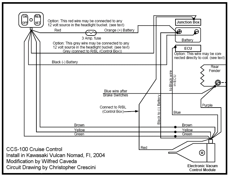
This project involves significant electrical wiring and requires modifications to the left side cover box, including drilling holes and making a slot. The gas tank must be removed, and careful reading of the instructions is essential. The Audiovox instruction...
Warning: include(partials/cookie-banner.php): Failed to open stream: Permission denied in /var/www/html/nextgr/view-circuit.php on line 713
Warning: include(): Failed opening 'partials/cookie-banner.php' for inclusion (include_path='.:/usr/share/php') in /var/www/html/nextgr/view-circuit.php on line 713