
555 electronic circuit diagram of a Christmas tree
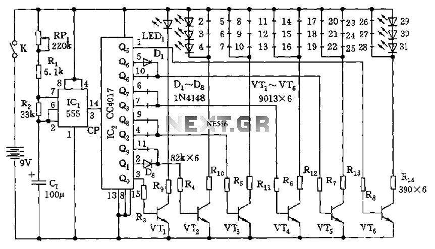
The circuit operates as follows: The astable multivibrator, constructed using the 555 timer, continuously generates a square wave output. The frequency of oscillation is adjustable through the resistors and capacitor selected, allowing the user to customize the blinking rate of the LEDs. The output from the 555 timer is fed into the CD4017 counter, which divides the frequency and produces a series of high pulses across its outputs Q0 to Q9.
Each high pulse activates a corresponding transistor (VT1 to VT6), which in turn drives the connected LEDs. The arrangement of the LEDs is designed to create a visually appealing display, lighting up in a sequential pattern that enhances the festive atmosphere. The design ensures that as the counter reaches a count of seven, a specific sequence of LEDs (LED28 and LED1) is illuminated, providing a distinct visual cue before the cycle restarts.
This circuit is ideal for decorative lighting applications, particularly during festive seasons where visual effects are desired. The use of a 555 timer ensures reliability and ease of adjustment, while the CD4017 counter efficiently manages the distribution of the pulse signals to the transistors and LEDs, resulting in a synchronized lighting effect that can captivate viewers. The overall design is straightforward, making it accessible for both hobbyists and professionals interested in creating dynamic lighting displays. As shown, the circuit includes a clock pulse generator, and a pulse distribution circuit drives the display circuit. 555 and RP1, R1, R2, C1 composition astable multivibrator, the oscillation frequency f 1.44/(RP1 + R1 + 2R2) C1. Oscillation period T 1/f 0.5 to 15 seconds, adjustable. Its output as the count clock IC2, IC2 decimal counter/pulse distributor CC4017, under the clock action, Q0 ~ Q9 successively appear high pulse, the pulse width of the clock cycle, the corresponding VT1 VT6 turn saturated conduction, the corresponding light-emitting diodes LED1 ~ LED31 various quarters were lit like a Christmas tree properly arranged, like the stars shine, enhance the festive atmosphere. After IC2 count seven, VT5 VT1 saturated conduction sequentially, LED28 LED1 lit in turn. Again and again, endless cycle.
Related Circuits
The danger always exists when fuel gases such as propane or natural gas are confined to a small area. The toxic gas alarm utilizes a tin-oxide semiconductor. A coil of thin wire is heated by a 12 V battery...
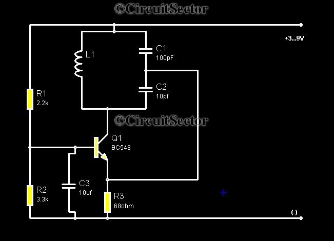
Metal detectors are typically complex devices that often incorporate expensive components, making DIY metal detector circuits uncommon. However, this metal detector hobby circuit can be built using only a few components, such as a BC548 transistor and a standard...
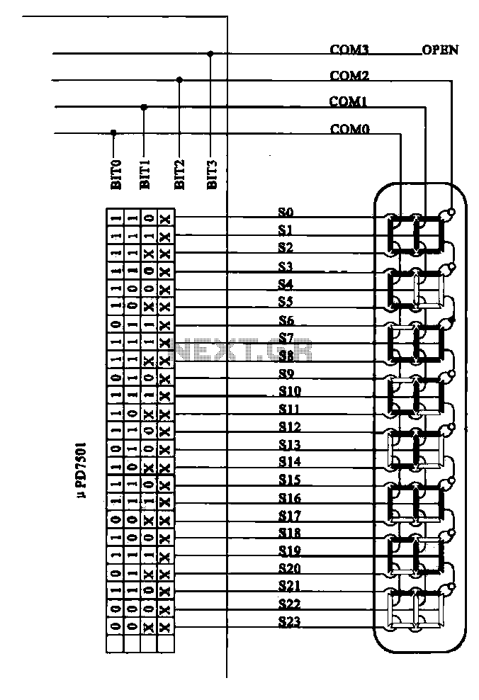
Examples of the structure of several liquid crystal display drive circuit CPU tubes. Liquid crystal display (LCD) drive circuits play a critical role in controlling the operation of LCD panels, which are widely used in various electronic devices. These circuits...

Intercom walkie-talkies represent an advanced application of crystal oscillators for voice transmission. Utilizing a crystal-locked oscillator for voice transmission is complex due to the oscillator's fixed frequency, which is challenging to modulate. The primary method for achieving this involves...
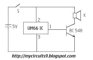
This is a circuit diagram for a simple doorbell. The circuit can be assembled indoors, while the switch should be placed outside, making it easily noticeable for visitors. The operation of this circuit is similar to a previous project. The...
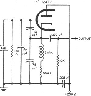
To update the fundamental oscillator circuits, simply replace the transistors with tubes. Alternatively, if one owns a vintage vacuum tube radio, it may be of interest to learn about historical practices. In general, the foundational principles of electronic circuits...
Warning: include(partials/cookie-banner.php): Failed to open stream: Permission denied in /var/www/html/nextgr/view-circuit.php on line 713
Warning: include(): Failed opening 'partials/cookie-banner.php' for inclusion (include_path='.:/usr/share/php') in /var/www/html/nextgr/view-circuit.php on line 713