
free diy open source boost driver

The boost driver circuit is a type of DC-DC converter designed to step up the input voltage to a higher output voltage. This circuit is particularly useful in applications where the power supply voltage is lower than the required load voltage. The fundamental operation of a boost converter is based on the principle of energy storage in an inductor, which is then released to the output at a higher voltage.
A typical boost driver circuit consists of several key components: an inductor, a switch (usually a MOSFET), a diode, and a capacitor. The inductor is connected to the input voltage source and the switch. When the switch is closed, current flows through the inductor, storing energy in its magnetic field. Once the switch is opened, the inductor attempts to maintain the current flow, causing the voltage across it to increase. This higher voltage is then directed through the diode to the output capacitor, which smooths the output voltage.
The control mechanism of the boost converter is crucial for regulating the output voltage. This can be achieved using a feedback loop that monitors the output voltage and adjusts the duty cycle of the switch accordingly. Common control methods include voltage mode control and current mode control, each having its advantages in terms of stability and response time.
In terms of component selection, the inductor must be chosen based on its inductance value and current rating, which should exceed the maximum load current. The switch should be a low on-resistance MOSFET to minimize power losses, while the diode must be a fast recovery type to handle the reverse recovery time effectively. The output capacitor should have a low equivalent series resistance (ESR) to reduce ripple voltage.
The design of a boost driver circuit can be optimized by simulating the circuit using software tools to analyze the performance under various load conditions and input voltages. This enables the designer to fine-tune component values and ensure the circuit meets the desired specifications.
Overall, the boost driver circuit is an essential component in various applications, including battery-powered devices, LED drivers, and renewable energy systems, where voltage conversion is necessary to meet the operational requirements.How would you like free boost driver designs?! Though I can`t control anyone`s actions, I would appreciate it if anyone wishing to sell this circuit.. 🔗 External reference
Related Circuits
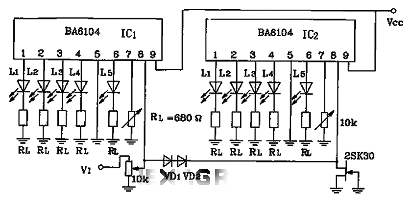
BA6104 is a five-digit LED level meter that functions as an LED display driver integrated circuit (IC). The configuration of the circuit is illustrated in the accompanying figure. The circuit utilizes a 10 by two-dot LED level display. The...
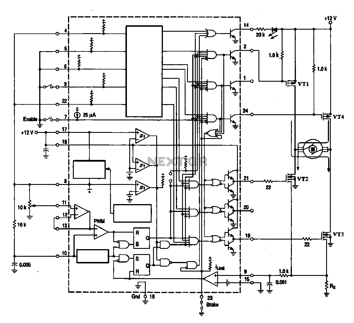
A DC brush motor driver circuit diagram utilizing the MC33035 chip is presented, illustrating a typical configuration for driving a straight DC brush motor. The circuit incorporates a field-effect transistor (FET) bridge driver setup. When transistor VT3 is activated,...
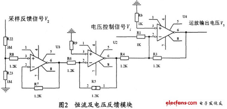
The output current range of the parameter current regulator is limited, and its precision is not high. Connecting the feedback adjustment type output current of the current-stabilized power source in series results in lower efficiency. The steady current source...
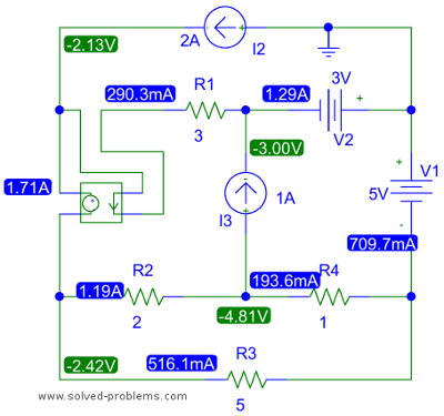
The top right node is connected to two voltage sources and contains three elements. All other nodes also have three elements. The selection of the top right node is significant because it allows for the determination of the node...
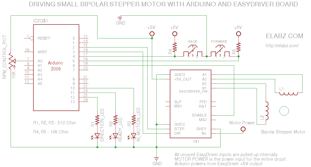
A simple circuit designed for testing bipolar stepper motors or for manual positioning using stepper motors. Schematics, Arduino sketch, and video are available. This circuit serves as a versatile tool for both testing and controlling bipolar stepper motors, which are...
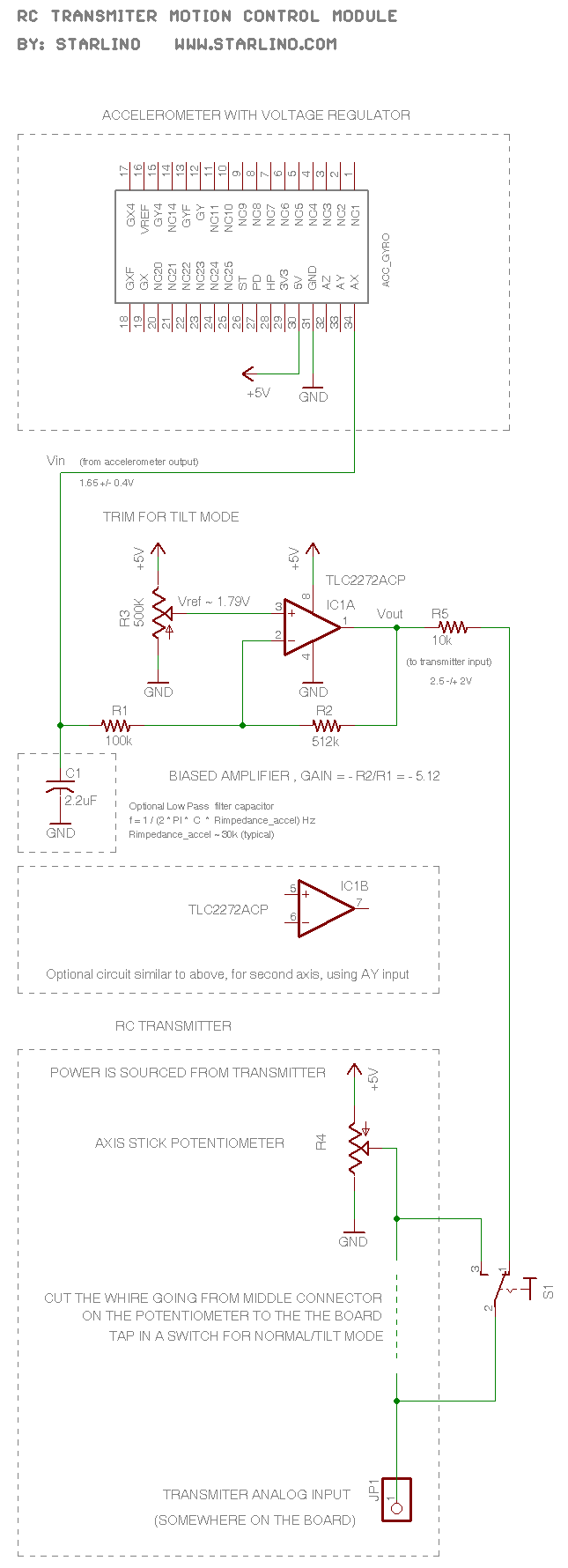
The RC transmitter utilizes a potentiometer for each axis, functioning as a voltage divider that outputs a voltage of 0.5V, with the middle position corresponding to 2.5V. This voltage is sent to the analog input, which is converted into...