
Combined Light-/Dark-Activated Switch Circuit
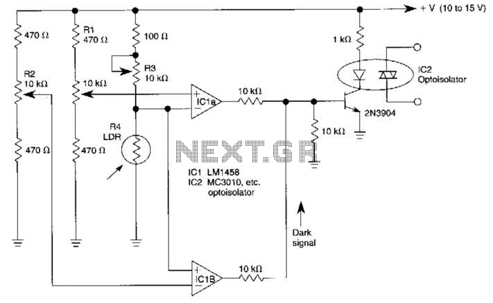
The circuit employs two operational amplifiers (op-amps) arranged in a bridge configuration, which is effective for comparing voltage levels and detecting variations in light intensity. The use of a bridge circuit allows for a differential measurement of light levels, enhancing sensitivity and accuracy.
Potentiometer R2 is crucial for calibrating the threshold at which the circuit will respond to low light conditions, effectively setting a baseline or dark level. By adjusting R2, the user can define the minimum light intensity that will trigger a response from the circuit. Conversely, resistor R1 is employed to control the upper threshold or light level, allowing the circuit to discern when ambient light exceeds this predefined limit.
Resistor R3 plays a vital role in the circuit by ensuring that a specific amount of current (approximately 1A) is present across resistor R4 at the designated light level. This configuration is essential for establishing a reliable reference point for the op-amps, enabling them to accurately compare the input signals from the light sensors.
The optoisolator IC2 is integrated into the circuit to provide electrical isolation between the sensor circuit and the load, enhancing safety and reducing the risk of interference. The trip points set by resistors R1 and R2 determine the operational state of the optoisolator, allowing it to activate or deactivate based on the ambient light conditions. This functionality is particularly useful in applications such as automatic lighting systems, where the circuit can control lighting based on the surrounding light levels, ensuring optimal energy efficiency and user comfort.
Overall, this bridge circuit configuration with op-amps and an optoisolator provides a robust solution for light level detection, with adjustable thresholds for varying ambient conditions, making it suitable for a wide range of electronic applications. Two op amps used in a bridge circuit configuration detect high and low light levels. Potentiometer R2 sets the dark level and Rl controls the light level. R3 is set so that about lA the supply voltage appears across R4 at the desired light level. Rl and R2 set the trip point of the optoisolator 1C2 at darker or lighter ambient levels, as required. 🔗 External reference
Related Circuits
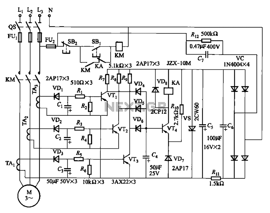
The current detection signal is obtained from three current transformers after rectification and filtering, resulting in three DC voltage outputs. These voltages are applied to transistors VT1, VT2, and VTa between the base and emitter. The signal is amplified...
This circuit is designed for use in a hi-fi showroom, allowing for the selection of different speakers to connect to a stereo amplifier for comparative listening. It can also serve similar applications where only one device from a set...
The circuit operates by utilizing a high-frequency section of the antenna to receive AM radio signals, amplifying radio-frequency signals at a selected vibration level of 465 kHz. The intermediate frequency (IF) signal is processed through an IF amplifier, followed...
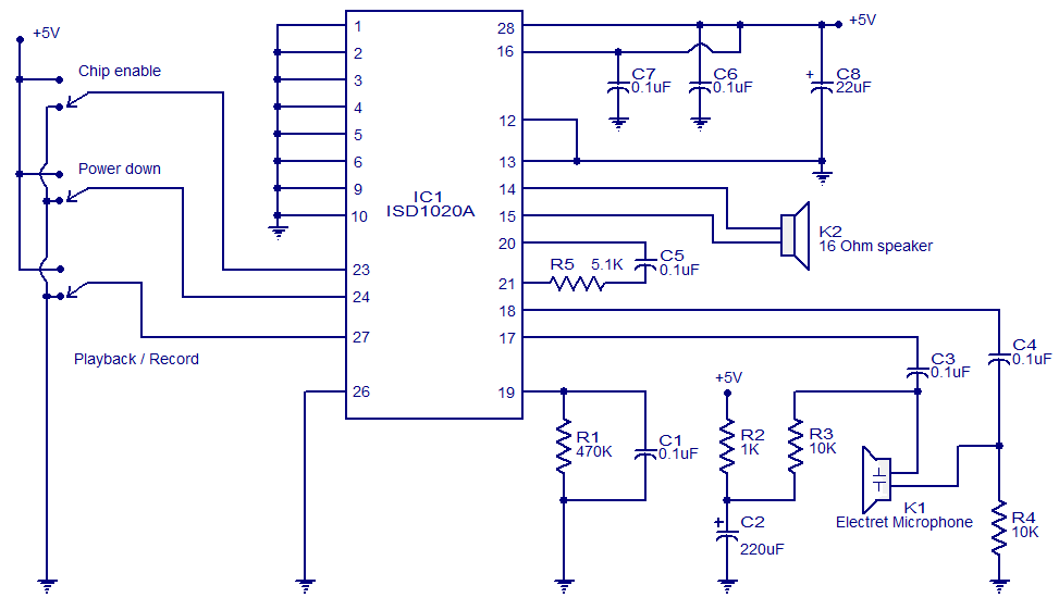
This circuit is designed in response to a request made by Mr. Vignesh for a voice recording and playback system. The circuit utilizes the ISD1020A IC from ISD, which is a CMOS single-chip record/playback device capable of recording voice...
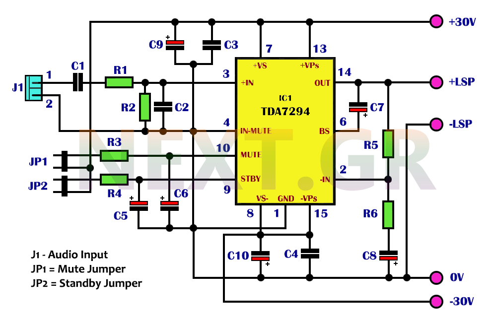
The integrated TDA7294 from SGS Thomson is a high-frequency acoustic power amplifier that boasts true high-precision specifications, making it suitable for various applications. Its standout feature is the significantly higher output power compared to typical amplifiers with similar distortion...
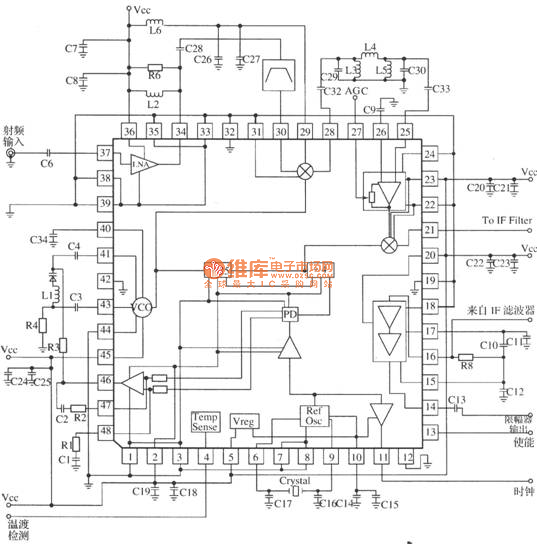
MRFICl505R2 is a 1.575GHz GPS downconverter chip. It integrates a mixer, VCO, PLL, crystal oscillator, A/D converter, loop filter, and other circuits. The MRFICl505R2 IF output frequency is 4.1MHz, with a typical conversion gain of 105dB, an operating voltage...