
Combustible gas alarm circuit diagram 2 7806 KD28
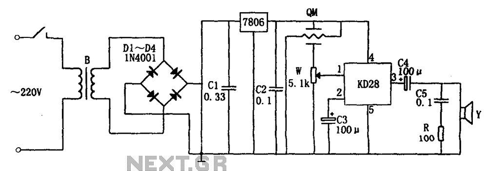
The gas detection system is designed to monitor the presence of flammable gases in the environment. The core component is the gas-sensitive sensor (QM-N5), which operates based on changes in resistance in response to gas exposure. The sensor is connected to a buck rectifier circuit that efficiently converts the input voltage to a lower output voltage suitable for the integrated circuits and other components. The buck regulator utilizes a transformer and a bridge rectifier configuration (D1-D4) to ensure a stable power supply, while capacitors C1 and C2 filter out voltage ripples, providing a smooth DC output.
The integrated voltage regulator (7806) maintains a constant output voltage of 6V, essential for the reliable operation of the KD28 integrated circuit, which is responsible for processing signals from the gas sensor. The adjustment potentiometer (W) allows for calibration of the sensor's sensitivity, enabling the user to set the threshold for gas detection. Initially, when the environment is free of flammable gases, the high resistance of QM results in a low voltage at the input of the KD28, keeping the alarm system inactive.
Upon detecting flammable gas, the resistance of QM decreases significantly, causing an increase in voltage across W. This change triggers the KD28 to activate the output, which energizes the speaker (Y) to emit an alarm sound, alerting individuals in the vicinity. The system is designed to revert to its normal state automatically once the gas concentration falls below the detection threshold, ensuring continuous monitoring without manual intervention. This gas detection circuit is suitable for various applications, including industrial safety systems, home gas leak alarms, and environmental monitoring setups. As shown in FIG alarm by a gas-sensitive sensor element QM, buck rectifier and regulator circuits, integrated circuits KD28, speaker Y and other components. Gas-sensitive senso r element QM is QM-N5 type. Buck regulator circuit by a transformer rectifier and B, the rectifier bridges D1 ~ D4, C1, C2, integrated voltage regulator 7806 and other components.In operation, the adjustment potentiometer W, so energized for 1 minute. When the air is clean, QM corresponding resistance value is large, the partial pressure of the small W, so that the KD28 reset the alarm does not occur.
When flammable gas when in contact QM, QM corresponding resistance value is small, the pressure on the larger points W, so that the KD28 set, 3 feet high output speaker promoting work, an alarm signal. After the gas leaves the circuit will resume normal operation.
Related Circuits
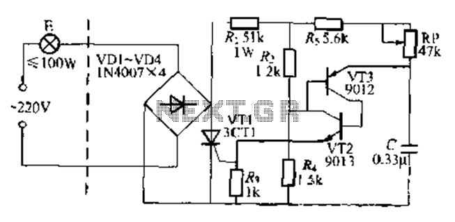
The circuit is a one-way ordinary transistor-triggered dimmer light circuit. It uses a complementary amplifier configuration with transistors VT2 and VT3 to form the thyristor trigger circuit for VT1. The circuit operates with a 220V alternating current through the...
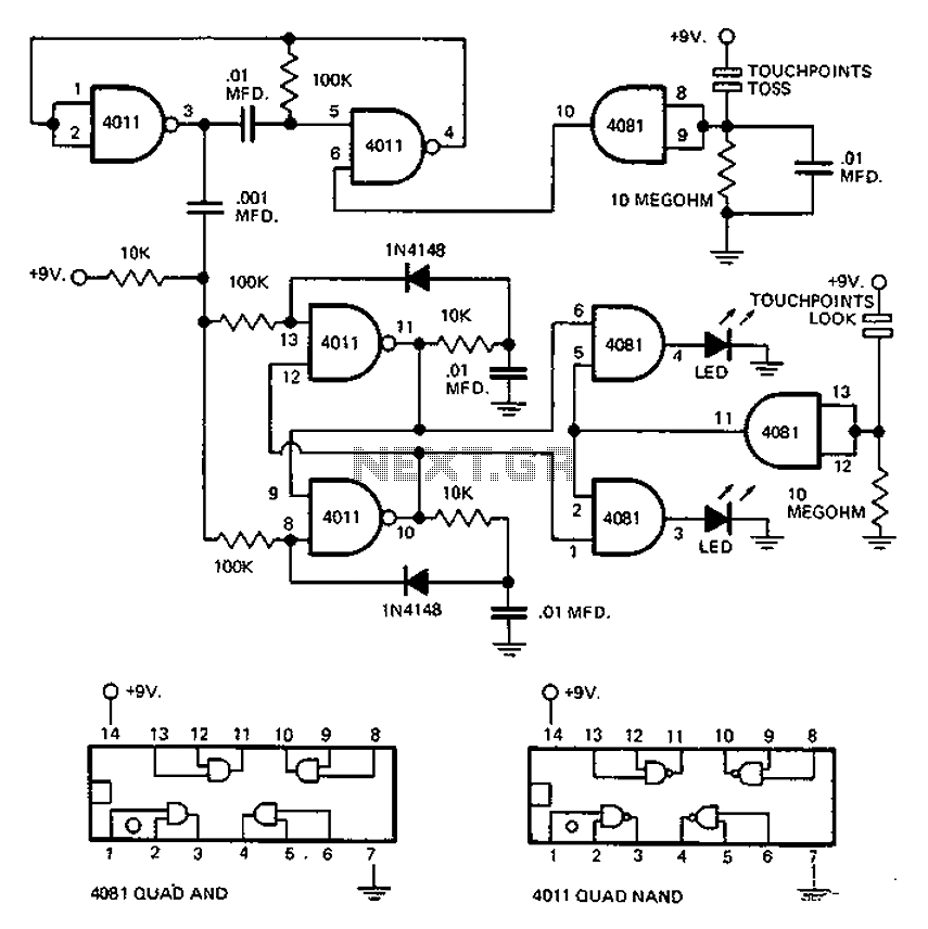
This circuit employs an astable multivibrator to alter the state of a signal based on specific conditions. It also incorporates a flip-flop, which retains the state of the output once a change is detected, completing a cycle of the...
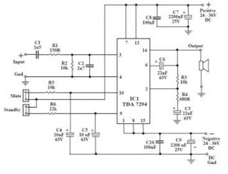
This audio amplifier circuit utilizes the TDA7294, a power integrated circuit designed for high-quality audio applications. The TDA7294 operates as a class AB amplifier, characterized by low noise and distortion levels, a wide bandwidth, and robust output current capability....
This is a small electronic switch that connects a battery to the equipment for a certain amount of time when a push-button is momentarily pressed. The ambient light level has also been considered; when it is dark, the display...
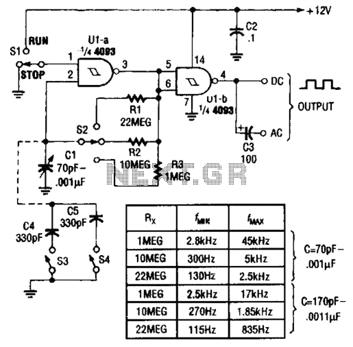
Two gates of a Quad 4093 are utilized in an astable multivibrator configuration. CI is a three-gang 365 pF variable capacitor with its sections connected in parallel. Additionally, S3 and S4 serve to switch in optional extra capacitors. The described...
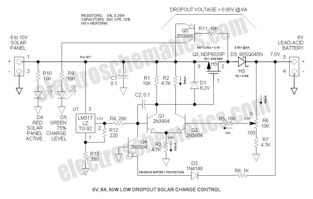
This Low Dropout Voltage (LDO) solar charge controller utilizes a straightforward differential amplifier combined with a series P-channel MOSFET linear regulator, ensuring compatibility and efficiency in solar energy applications. The Low Dropout Voltage (LDO) solar charge controller is designed to...